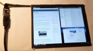
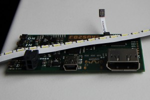
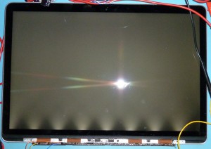
Author Archives: mike

Miscellaneous updates, 2013-12-04

Oops!  I told myself I would update this site at least once a month.  As you can easily see, I haven’t quite kept up with that desire.  Things have picked up in my professional life and I have not had nearly as much time lately to tinker with this stuff.  But here’s what’s going on.

  • iPad simple interface:  Currently out of stock.  I’ve sold all of my first-run boards and have not ordered more.  Sources for some of the components used have dried up, and I may need to change the board to accomodate replacements.  Additionally, based on the results of the Macbook board, I might want to add some small power supplies to the board to alleviate the need to provide two precisely regulated rails.  There is currently no ETA on this.
  • Macbook board:  Hasn’t been touched since the previous post.  Lack of time, unfortunately.
  • iPad digitizer research:  Starting up again.  The next “real” post may well be on this topic.
  • Other in-progress projects:  No further progress.
  • Metalworking:  I am now the proud owner of a Precision Matthews PM-932M mill/drill machine, so one of these days I’m planning a new series on making metal widgets.  Stay tuned for that.

Also please note:  The server on which this site resides is due for major hardware changes in the next week or two.  Expect downtime of up to a day or two while new hardware is installed and configured.  I suspect I’ll be too lazy to put up a “down for maintenance” message, so this will be the only warning.  Don’t worry, unless there’s some major hardware issue the site will be back soon.  [Edit: Complete.]

So that’s where I’m at.  No real news to pass, but it’s high time I posted “something” so folks don’t think this site is abandoned.  Hopefully the new year will bring more time to work on some of these in-progress half-finished projects.  We’ll see.

Hacking the Macbook Pro Retina LCD, Part 4: First PCB Tests

Welcome back!  It’s been more than a month and a half since my last post on the Macbook Pro Retina panel – damn my “real job” and the time it consumes.  But we’re here now, so let’s dive into things.

In the previous two posts on this subject, I have talked about two boards that I have been developing for the 15.4″ Macbook Pro Retina display assembly: a breakout for the FaceTime camera, and the main display controller / backlight driver board.  Well, in the month-and-a-half that has elapsed, both boards have been received and built.  Let’s start by taking a look at the former.

Camera Breakout

When I went to order these boards, I did so immediately after the cutoff for the current OSH Park 4 layer order, so the estimated delivery time was three or four weeks.  Unhappy and impatient, I held off and instead ordered the board as 2-layer for more instant gratification.  The two inner layers are only GND, so this is possible without too much trouble.  It throws off the impedance of the USB traces probably significantly, but as the entire trace length is a half inch or so, I figured it’d be close enough for at least temporary use.

So the boards arrived a week and a half later.  I immediately noticed something interesting and bothersome.  Board fab houses typically require a gap between the edge of any copper and the routed board edge.  If you are making a small board and including mounting pads for screws, the pads may consume a large percentage of the total board area – in fact, the pads may well drive the overall dimensions of the board, and larger dimensions mean greater board cost.  I wanted this board to screw mount, but even the 2-56 screws I designed for needed quite significant pads.  I decided it would be nice to trim the amount of room wasted on mount pads by clipping the pads at the board edge, allowing the screw to extend into the no-copper area at the edges of the board – it really only drops a few cents from the board in this case, but it makes me feel better.

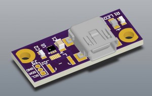
So in Altium Designer, I made a small Pad on Multilayer (the magic layer which is copied to all other layers), then made a Polygon in the shape of a circle with a flat edge and also placed this on Multilayer.  In theory, this should have resulted in a round pad with a flat edge, drilled and plated through as expected – in fact, the 3D render of the board shows this:

For a sense of scale, remember that that's a miniUSB...

Mount pads look OK here.

But what arrived from the fab was this:

There aren't supposed to be voids in those mount pads...

There aren’t supposed to be voids in those mount pads…

When I poured the rest of the GND polygon, apparently Altium attempted to connect to the inner Pad, and generated Polygon Cutouts surrounding it, which happened also to cut the Multilayer polygon.  It didn’t show in the PCB editor, although it did in the Gerbers – but I was in too much of a hurry when ordering to notice.  Oops.  But so be it, it’s only the mount pads.

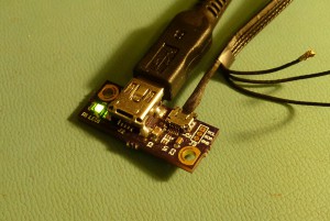
I then assembled the board, and with bated breath, plugged it into a USB port.  And Hooray!  The Device Connected sound sounded, and the camera showed up in device manager.  But, strangely, the power LED was orange.  I specified a green LED, I thought I placed a green LED, but it was bright orange.  I checked the package to be sure but it was correct.  It was then that I discovered a tiny short, and simultaneously learned that if you apply 5V directly across a 2.1V green LED, it becomes an orange LED.  Neato!  It also gets real real hot.  But miraculously, after I corrected the short, which had caused the full USB voltage to appear across the LED, it returned to green and operated as normal.  So I guess I can say, these OSRAM CHIPLED parts seem to be pretty hardy!  I unfortunately don’t have any photos, but these parts are cheap, so buy some and experiment for yourself.  Science!

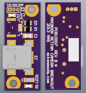
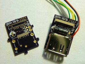
After a few days the 4 layer board order deadline had arrived again, so (having not discovered nor corrected the pad issue) I re-ordered the board as 4-layer, this time adding a second transient suppressor for the ALS connector… because why not, and you can always short it with jumper wires if you don’t want to use it.  So here’s what that looks like (note that I have fixed the pad issue at this point):

Yep.

Yep.

I haven’t bothered to build this one yet, but it hasn’t changed significantly since the 2-layer version, so I suspect it’ll work fine.  The files for this board can be downloaded here:

Enjoy!

Main Controller Board

Now, the information you’ve all been waiting for.  As I said on the previous post on this subject, I quickly threw together this board to get it in before the following OSH Park cutoff.  As such it’s not perfect, but it is fairly functional (or so it seems from the minimal amount of testing I’ve done so far).

There’s a lot of new stuff going on on this board, as compared to my iPad board (on which this one is loosely based).  Of course the panel output connector is different, because the panel is different.  Also, though, the barrel jack has been removed, and a 2-pin shrouded connector has been added in its place.  Barrel jacks, I finally came to realize, are just too damn big and expensive for a little cheap board like this.  The new solution is less than a dollar in single quantities for plug, receptacle and terminals, whereas the board mount barrel receptacle was more than a dollar by itself, not counting wire mount plug.  Plus the barrel jack tended to be the tallest component on the board, driving enclosure dimensions.  It takes a bit more work to implement, but I still think this was a good change.

The dc-dc converters are new as well.  The board contains two dc-dc buck regulators, both based on the AOZ1281 from Alpha & Omega Semiconductor.  This part was chosen due to very low cost – about $0.90 in single quantities – as well as ample output current (1.8A) and acceptable input voltage range (3-26V).  The board implements this part as one 3.3V/500mA converter and one 3.8V/1A converter, the former for processor, indicators and other functions, and the latter for the panel itself, which was investigated and found to run well on 3.8V in a prior post.  It’s probably a 5V panel, in retrospect, and I may someday become ambitious enough to test it at this higher voltage, but for now 3.8V works.

The board shares the same Freescale MKL25Z128VFM4 processor as the iPad board, again due to cost to performance ratio of the $3 ARM Cortex-M0+ core.  Sure, I could drop $0.50 and put in a MSP430, but I like the potential for other functions that the more powerful processor enables.  I still need to learn how to program the damn things, but I digress.  The other big IC on the board, the backlight driver, has completely changed compared to the iPad version.  Whereas the iPad panel has 12 backlight channels at 20V apiece, the Macbook has only six channels but at some 52V.  The LT3754 used on the iPad board only does 45V, so a new backlight driver is needed.  Of the (relatively few) integrated boost converter / LED driver ICs, the best choice for this application seemed to be the Freescale MC34844A, which happily will push out 60V with appropriate configuration.

In the interest of keeping this post from being more than fifteen or twenty pages, I’ll leave the rest of the description to the schematic, but if anything is unclear please feel free to drop me a comment or email.

Again, this board uses 2-56 mounting screws, and again, I opted to include clipped pads.  And again the boards showed up with voids in the pads.  But this time, inexplicably, some of the pads did not have voids.  They were all created the same way so I can’t quite explain that one yet.  But one thing is for sure, I’ll certainly pay more attention from here on out.  I built the pads for one of my boards at work with clipped edges as well, but this time used top and bottom polygons instead of one multilayer one.  In this way the pads are slightly smaller in the internal layers, but on the other hand the polygons connect without issue, so that’s a small price to pay.

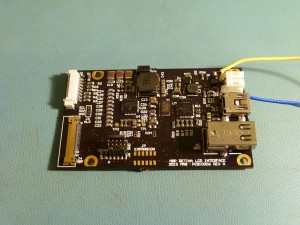
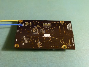
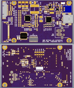
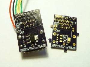
Anyway.  Here’s the (99%) finished board, lacking only a fuse and transient suppression diodes in front of the USB port and DP connector:

Top.  Ignore the soldered-on power wires...

Top. Ignore the soldered-on power wires.

Bottom.

Bottom.

I’m not 100% happy with it – in particular, I suspect that my overzealous attempt to match the lengths of the DisplayPort lanes may have actually had an adverse effect on signal integrity as the traces have to bend a whole lot and come in much closer range of each other than is really recommended.  But I can say that the board works like this, and I can’t keep from releasing something forever because I’m not 100% happy with it (or so my boss always says – “You can always fix it in Rev B”).  So here we are.

Now, the processor has control over panel power and backlight on/off and brightness, so without programming the processor the board won’t do anything.  So, still lacking much experience with the ARM Cortex-M0+ platform, I wrote a very barebones program that simply turns on the power and backlight driver for the panel, and additionally powers up the PWM controllers for the offboard indicator LED.  So here’s the board documents, and the source to at least power-on the necessary systems:

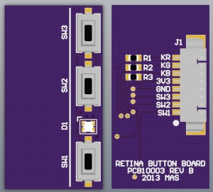
Holy cow, I just realized I never released the documents for the indicator/button board either!  Well, let’s go ahead and do that now too.  Here’s what it looks like:

Pretty simple.

Pretty simple.

This board is designed to be double-stick taped directly to the back of a panel at an edge of your choosing (my preference is bottom-right) and connected to the main board via a wire harness.  Some of the other controller boards out there with buttons onboard have very awkward button placement, so this is a slightly more expensive but much more elegant solution.  The files for this board are attached here:

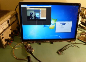
Whew.  This has been a grueling post to prepare.  Enough for now.  Er, except for one last picture!

Woohoo!

Woohoo!

<< Previous post in this series

Miscellaneous updates, 2013-08-27

It’s been quite a long while since I’ve posted anything, so I just wanted to put something up to reaffirm that I’m still here 🙂

It has been a busy few weeks for me in the world  outside my workbench, so progress has been slow on the active projects.  Here’s an overview of what’s going on:

  • Macbook “full-featured” controller board:  Boards hare arrived, waiting on component delivery (due Thursday).  This will include demos of some new and lower-cost components which will eventually make their way into other boards.
  • iPad “full-featured” controller board:  On hold pending redesign for cost reduction and results of Macbook hardware evaluation (as much of the hardware is shared).  Will leapfrog the Macbook and iPad boards until I am satisfied with how they work.  Also am working on the software for this board.  I’m really trying to get a USB firmware update utility built, but I’m new to the Kinetis platform so I’m having some trouble.  Has anyone out there built a DFU loader for a KL25 that can share some pointers? 🙂
  • Macbook camera board:  I ordered a 2-layer version (inner layers are all GND) some weeks ago to test, and that worked fine.  Now the proper 4-layer boards are in and I need to build one of those up.  But I’m satisfied with the design in general so I should be releasing those documents as soon as I get the ambition.
  • iPad touch panel:  Oof… haven’t touched that one for a while.  Need more free time…
  • Reflow oven:  I found some proper convection-type ovens at the local Wal-Mart for around $40 which will save me plenty of work in installing my own stir fan, so I may well be starting over.  For now I’m getting too comfortable running the boards freehand with a temperature probe though…
  • LP173WF2: Working on an interface board to take advantage of the connector hack I implemented.  In progress, no ETA

So that’s that.  Not much to show at the moment.  But hopefully that’ll change this weekend when I get some work done on the Macbook boards.

Plus!  I just this weekend got my new milling machine up and running!  So expect some metalworking projects to start showing up from time to time.

That’s all for now.

[EDIT 9/9/13] Hey, progress!

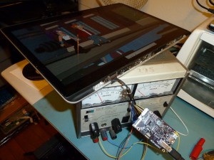
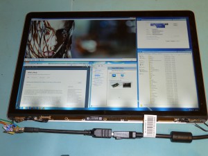
Good ol' high-definition Futurama.

Good ol’ 2880×1800 Futurama.

The Macbook board mostly works!  Backlight driver is putting out on the low side of its designed voltage and the firmware is only complete enough to force everything on, but other than that, it seems to run pretty OK.  Full post on this hopefully tomorrow.

Hacking the Macbook Pro Retina LCD, Part 3: First Working Demo

After screwing up and designing boards around an incorrect connector, and then when the corrected boards came in immediately leaving town for a week on business, I’ve at long last had some time to work on the Macbook panel.  Spoiler alert:  Some progress has been made.

If you don’t recall from previous posts, I threw together a quick board containing only DisplayPort and I-PEX connectors and a bunch of pin headers between them.  The idea is that since we know where the DisplayPort connections are but not the order in which they are arranged, we can solder in jumper wires very easily to test the various lane orderings and polarities without having to otherwise modify the board.  Here’s (the fixed Rev B version of) the board I used to figure out the pinout:

Assembled test board with all wires attached.  I unfortunately don't have a photo of the board prior to installing the wiring.

Assembled test board with all wires attached. I unfortunately don’t have a photo of the board prior to installing the wiring.

There’s nothing special going on here.  At top, connected to the panel, is the I-PEX connector, with its known power and backlight pins hardwired in.  At the bottom is a standard mDP, connected to the host PC.  I connected all the wires I could – power and backlight of course, and AUX+ and AUX-.  From there some engineering is required.

First, we look for Hotplug Detect.  This pin should go logic high shortly after power is applied to the panel.  There are only two pins left on the connector without a defined purpose, 9 and 10.  In testing the panel, it is observed that pin 9 develops 2.8-3V, and pin 10 develops 1.4-1.7V.  The latter is a bit low for HPD, so we will assume that pin 9 is HPD and pin 10 remains unknown for now.

With that pin now connected, we begin testing the DP lanes.  Remember that logically, the lanes should be arranged in one of four orders: 0+/0-..3+/3-, 0-/0+..3-/3+, 3+/3-..0+/0-, or 3-/3+..0-/0+.  I started with the first ordering listed.  Interestingly, the display showed a half-inch of garbled blue blocks at the top and gray bands down the rest of the surface, but the display announced itself to the PC properly and I was able to set its properties.  More boggling yet was that when I reversed the polarity of each of the four pairs, I got a different garbled top area (this time more like static) and the same gray bands, but equal operation with the PC.  I had always assumed that the incorrect polarity would result in a completely inoperable display – interesting.  But not yet correct.  I tried the other two combinations, and neither of those would even bother to talk to the PC beyond sending EDID.

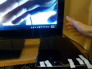
I panicked for a second here, thinking I’d have to try a lot more combinations of pinouts, taking a lot more work.  I tried just connecting one, two or three lanes to see if that made any difference but the PC was unhappy with all of these tests.  Finally I happened to glance at the analog ammeter dial on my bench supply and it was wiggling fairly wildly around the 300mA range.  This didn’t seem right at all, and I immediately began to suspect the power I was applying to the panel (through about three feet of jumper wires to place it close enough to the DisplayPort source on the other side of the room).  When I replaced the original pinout (with the blue blocks) and used about 8″ of hard-soldered wire and a local bench supply, and upped the current limit to about 1A, I was greeted with the following!

It works!

It works!

This just goes to show you how important it is to pay attention to the impedance and voltage drop of your wiring.  Always use as short of wires as possible!  Do note that I only connected one backlight string, which is why the banding is so bad; with the other five strings connected it probably wouldn’t be noticeable.  It looks a little dark because I don’t have proper current limiting installed and I’m driving it cautiously.

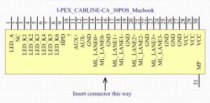
So now we know the full pinout of the Macbook Pro 15.4″ panel (or, at least enough of it to get it running.  Here it is, for your design and hacking purposes:

Not sure what Pin 10 is.  Looks kind of like 0.5*HPD

Not sure what Pin 10 is. Looks kind of like 0.5*HPD

Finally knowing the pinout, and running short on time before the next OSH Park 4-layer order, I quickly made up a proof-of-concept controller board for the panel.  The board includes a Freescale MC34844A backlight driver, a Freescale Kinetis MKL25Z128 ARM Cortex-M0+ processor (again chosen for cost to performance ratio), independent switching supplies for the processor and for the panel (which requires a different voltage), mini-USB and mini-DisplayPort connections to the host PC, and a header to match the header on the camera board for the ambient light sensor.  Special care was taken to cut costs on this board wherever possible without compromising functionality – the Linear Technology switcher from the iPad board was scrapped for parts a third of the cost, and some parts were increased in size to avoid paying the premium for the size decrease.  With some difficulty the board was kept to the same compact 1.5×2.5 inch form factor as the full iPad board.

I don't have many of the parts modeled yet.  So sue me, I was in a hurry!

I don’t have many of the parts modeled yet. So sue me, I was in a hurry!

I will release the documents for this board as soon as I build one up and verify that it works – I don’t want anyone ordering a board which might not work.  If you still really want them ahead of time to look at, send me an email.

<< Previous post in this seriesNext post in this series >>

A Compact FullHD 120Hz 3D Display, Part 1: First Looks

Last week I wandered across a thread over at the Overclock.net forums talking about my iPad controller boards.  It would seem there is a growing demand for ultra-high-resolution multi-panel displays amongst the gaming and power user crowd.  The recent releases of high-pixel-density panels in consumer devices means they have become quite accessible to the average hobbyist.

There are a couple of niches that these panels best fill.  For the road warrior, the compact size of the iPad panel might be nice.  For the graphic designer, the Macbook Pro Retina panel offers good performance.  But for the gamer crowd, where high refresh rate is most desirable, neither of these panels quite fits the bill.

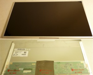
As it so happens, boutique PC manufacturer Alienware continues to push the limit (and budget) of the gamer-on-the-go.  Enter the Alienware m17x, a megalaptop with an optional 17.3 inch, 120Hz, full HD 1080p, 3D-capable display.  That’s an awful lot of display, and found in its native habitat the privilege of using it would start at $2000, but thankfully we can find replacement panels in the usual places for about $100.

Now, 1080p doesn’t really hold a candle resolution-wise to some other panels such as the Macbook Pro Retina display at 2880×1800.  But the major advancement here is the 120Hz refresh rate, which promises to offer better gaming performance and less video tearing.  I don’t game much, but I was curious about the combination of features in this panel, so I bought one to play around with.

The panel in all its glory.  Note that I'd already removed the square of conductive shielding cloth before this photo was taken, which is why it is wrinkled.

The panel in all its glory. Note that I’d already removed the square of conductive shielding cloth before this photo was taken, which is why it is wrinkled.

This is the LG LP173WF2(TP)(A1).  We can pull all the necessary specifications from its datasheet (mirrored locally here).  It is driven with 4-lane Embedded DisplayPort, just like the Apple Retina panels.  However, interestingly, this panel is driven with 5 volts, instead of the typical 3.3V.  Further unexpectedly, the panel electronics draw a shocking 2.3 amps (11.5 watts), which does not include the backlight.  I bet the stock 86Whr battery in the m17x doesn’t last very long.

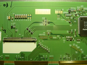
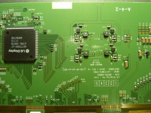
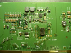
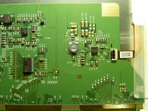
Speaking of the backlight, a notable difference between the Retina panels and this panel is that the LP173WF2 contains onboard backlight drivers, eliminating the need for external drivers.  SImply apply between 7 and 20V, a logic-high Enable signal and a 5-100% duty cycle square wave, and the rest is taken care of.  The backlight claims to draw another 11.6 watts.  Here are some high-resolution shots of the panel’s backlight drivers and controller electronics:
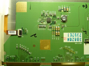
LP173WF2_Controller_1LP173WF2_Controller_2LP173WF2_Controller_3LP173WF2_Controller_4LP173WF2_Controller_5

Just like every new display, this panel has a different set of power and control requirements to all the others.  Thus, a new controller board will be designed to fit the particular needs of this unit.  But we’ll get to that in due time.

First, let’s take a closer look at what we’re working with.  Seemingly similar to every other panel, this one has a unique connector and pinout.  In this case it is a JAE FI-VHP series 50-pin connector, FI-VHP50S-A-HF11, mating connector FI-VHP50CL-A.  This is a problem for a couple of reasons – first, this appears to be a new part which is not currently available at any of the usual distributors, second, even if we could find it, it’s probably beyond the capability of most folks to populate the 0.5mm pitch connector with the very small (32-42AWG), preferably shielded coaxial wires.

So what do we do?  We could order a reel of 3000 pieces direct from JAE for some thousands of dollars, but that’s not a wise investment unless we’re likely to use a couple thousand pieces, and then we still need to assemble the harnesses (and soldering 50 tiny wires on 0.50mm pitch won’t be fun).  We could draw up a specification and order custom harnesses from a supplier, but still unless the quantities are quite high they will probably be more expensive than we’d like.  We could buy used assemblies from the source laptop on eBay, which we can get in single-piece quantities, but these are not very prevalent and are extremely expensive.  Or we could replace the connector with a more widely-used type, which requires us to modify the panel but is comparatively very inexpensive and easy to come by.  I have opted to take this last approach initially, and will reevaluate the other options if demand arises.

Originally I contemplated designing a flex circuit harness to solder directly to the panel and break out into an iPad-style 0.3mm contact pattern.  I still think this would have been a fairly slick solution, but when I attempted to draw it up I found that this contact pattern is not possible for the low-cost prototype houses to produce – the traces are too small and the pads are too close together.  So as a runner-up option I have chosen to replace the existing connector with a 0.5mm ZIF FFC socket, FCI 62684-501100ALF.  By using a standard connector like this we can also use standard FFC cable assemblies, which are very inexpensive and come premade in a variety of lengths.  I bought a 2-inch cable which seems about right.

Original FFC concept.  Ultimately this plan proved too complex for the "budget" flex board suppliers.

Original FFC concept, using my full-feature iPad board as a stand-in for the new board.. Ultimately this plan proved too complex for the “budget” flex board suppliers, and I was unwilling to pay for a “real” board house.

The downside to this approach is that since the VHP-series connectors have a 3-pin-wide break in the middle, the 50-pin connector is actually the width of 53 pins.  Luckily two of the pins on one side are No Connects, but we are still forced to choose between losing pin 1 (“2D/3D Contents Communication”) and pin 48 (DP Lane 3 shield ground).  I have opted to offset the connector to carry the ground connection, and will re-wire pin 1 to one of the three unused pins in the middle of the connector if I get around to it.  Actually if you look at the controller photos it appears as if pin 1 is connected through a non-populated resistor and is thus a no-connect, so I may not bother.

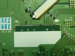
The removal of the existing connector took a surprising amount of effort.  The FI-VHP series has stabilizing legs soldered to the board on the three sides without contacts, so all four sides are soldered down.  This makes removal of the connector, particularly without harming nearby components, quite difficult.  To reduce heat transfer to the heat-sensitive plastic diffuser films, I propped the controller board up off the rear surface of the panel.  I would like to have flipped the controller board over and solder it against a flat surface to avoid stressing solder joints, but the board is held by a small jog in the plastic frame and I felt uneasy putting enough stress on the connecting ribbons to move it.

An embarassing amount of time later, the original connector was removed, losing only one mount pad and the two No Connect pads in the process (probably because my heat was too high):

Connector removed (but pads not yet cleaned), connector modified to clear U4, soldermask removed for side feet.

Connector removed (but pads not yet cleaned), new connector modified to clear U4, soldermask removed for side feet.

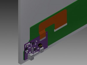
Now, to understand my next move, it is important to note my grand plan for this panel.  I’ll illustrate the plan with a 3D model as soon as I have time to draw something up, but for now words will have to suffice.  The panel will need to have a controller PCB attached, to generate the backlight dimming signal and break out the eDP to a more accessible connector.  The various connectors required and the cables attached to them are bound to be heavy, so I don’t want to attach my board to the thin plastic protective sheet over the LCD controller.  I’d much rather stick it directly to the exposed sheet steel chassis.  To achieve this the ribbon cable must point up.  I could either accomplish this by putting a sharp bend in the ribbon cable, or by populating the connector upside-down.  The latter option has the disadvantage of interfering with one of the eDP ESD protection diode arrays, but it provides the benefit of also allowing me to solder down the outer feet to provide strain relief to the tiny solder joints.  This is ultimately the path I chose.

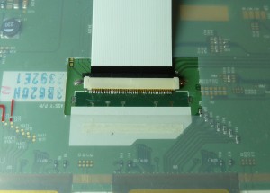
I scraped away some soldermask to make pads for the connector’s feet, and trimmed off the corner of the connector and latch to clear the protection diode.  Then, time to solder the pins.  I had some trouble getting the solder to flow between pin and pad – because the connector “only just” fits behind the diode, there is almost zero exposed pad behind each pin, which means there is no rear solder fillet to span the gap.  Probing the pins with a dental pick after the first pass noted several wiggling pins, on which solder had flowed over and up the pin but not down around it.  I went back and pressed down on each pad while applying a little more solder and that seemed to fix things.  And after more time than I am comfortable admitting to, and on my third connector after ruining two, it was finally done.  Here’s what it looks like now:

Looks pretty good, if you don't look too close.

Looks pretty good, if you don’t look too close.  Don’t let the photo size fool you, those pads are really really tiny.

Ultimately I was unable to reflow it with hot air and unable to solder it with the finest tip I had on my home soldering iron so I had to take it to work and use the professional soldering station there.  I often say that the things I design are difficult to build up, but for some reason – probably due to the delicateness of this assembly – this one was the most difficult soldering job I’ve recently had to do.  I sure hope a source for the correct connector appears, because this was no fun!  Actually, to be fair, after I started using the pro soldering station things went a whole lot better, so maybe if you have good equipment it’s doable.  But it’s certainly no cakewalk.

That’s about all I feel like doing for now.  I now need to spend some time hacking the other end of the ribbon into one of my iPad or Macbook boards in order to apply power to the panel.  As a happy accident, as I noted in an earlier post, I have a set of boards that I designed erroneously to break out a 0.5mm connector which I thought was used in the Macbook, so maybe I can leverage those to get up and running faster.  We’ll see.

Hacking the Macbook Pro Retina LCD, Part 2: The Camera

Something new and interesting.

So, my breakouts for the Macbook Pro Retina’s I-PEX display connector are finished and are on the way from the supplier.  This has been a long ten days.  But it’s not all roses, they’re set to arrive on Monday, the day I start a week of travel for work.  So there will be no fun display hacking time for the next week.  Oh well.

But in the meantime I have turned my attention to the other bundle of cables coming from the display – the antenna and camera connections.  The antennas aren’t all that interesting – we could use them, but they don’t provide a function on their own and the hardware necessary to make use of them would be more complex than it would be worth.  Plus both of my displays have the antenna wires cut.  On the other hand, the camera is a bit more useful.  And like the panel itself, it can be made operable with little more than a connector breakout.

Apple cameras (“iSight”, or more recently “FaceTime”, embedded cameras) have been USB based for a number of generations of MacBook, since at least 2006.  Similar to normal USB, the camera connector traditionally contains 5V, GND, and two USB data lines.  However in addition to this, most Apple camera connectors also carry an i2c interface.  We’ll talk about that a bit more later.

There are plenty of different Apple camera units, a unique one for each model and generation of Macbook.  Over the years they have been built in a number of different form factors, and have been terminated with several different types of connectors.  And within these connectors, the wiring has been arranged in several pinouts.  So while I have some Macbook schematics and know what to expect in general, it is not so easy as applying a “generic” pinout to this unit.

The Macbook Pro Retina display assembly’s camera connector is made by ACON (Advanced Connectek); the part number is currently unknown.  It’s a six-position connector with 0.4mm pitch, likely a solder-type part as the flat contacts appear to be integral to its body.  A bead of epoxy seals the wires into the connector.  Six individual black wires run from the connector to the camera.  The wires are somewhere in the 0.3-0.35mm diameter range, stranded, and uniquely jacketed – the black jacket appears to have a copper coating on the inside.  The wires are bound together with sticky black fabric tape and enter the display assembly on the righthand side of the bottom edge after about 150mm of free cable tail.  On the way it passes through the righthand hinge assembly.

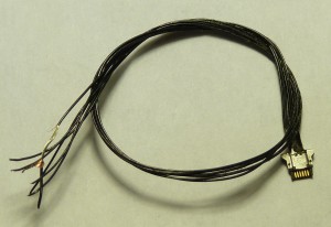
A Macbook Pro Retina camera cable, cut off a panel.  The copper foil jacket can almost be seen to the left.

A Macbook Pro Retina camera cable, cut off a panel. The copper foil jacket can almost be seen in the stripped wire to the left.

The camera module sits behind the main display glass.  According to the iFixit teardown of the Retina display unit, the glass can’t be reliably removed without damaging it.  Therefore it would be best to figure out the pinout without having to inspect the camera board directly.  The ideal way to do this would be to pull the pinout directly from the schematic, but as I have not yet found a schematic for the A1398 Macbook Pro, we must devise another way.

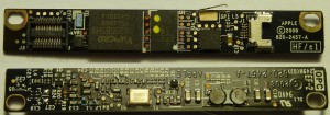
One way or another, a mate connector for the camera would be desirable, to avoid having to cut the cable.  As I have been unable to find a source of these directly, I bought a Macbook Air camera mainboard sans lens.  I was very careful to inspect the myriad Macbook cameras available, because many of these – INCLUDING the A1398 camera – appear to use FFCs or other types of connectors, which will not mate with the motherboard side of the camera harness.  Here’s the board I bought:

Macbook Air camera mainboard, unknown source model

Macbook Air camera mainboard, unknown source model

The side advantage of having an additional camera board to fondle is the ability to probe and investigate how Apple designs their camera boards in general.  So what have we here?  First we will evaluate the silicon present on the board.  The most prevalent IC is U2, a Vimicro VC0336BSHB USB webcam interface ASIC.  From the product brief, we can see that this chip talks to a CMOS image sensor over LVDS, has a serial interface for a flash memory, has mic inputs and an AC’97 codec interface and speaks to the PC over USB.

Next to this is a SST SST39LF010 1Mbit flash memory, which is probably where configuration information such as the USB device descriptors are stored.  Next to this is a suspiciously placed chip with a pair of inductors underneath, which predictably is a dual buck regulator, a TI TPS62402DRC (marking BYH).  This IC provides a fixed (1.8 or 1.2V)/400mA and 3.3V/600mA.

That’s enough to work with.  The datasheet for the TPS62402 notes that pin 8 is GND and pin 3 is VIN.  Some probing reveals that in the input connector beginning at the left (marked with a silkscreen arrow), pin 1 is +5V and pin 6 is GND.  This is reaffirmed by the connection between GND and the metal body of the connector.  While we’re at it, EN1, EN2 and DEF_1 are pulled to +5V, meaning both supplies are permanently enabled, and the output voltages are 3.3V and 1.8V.

Conspicuously, two of the remaining pins (4 and 5) are run through a common mode ferrite bead.  This wouldn’t make sense for an i2c SCL/SDA line, since the two signals are not complements of one another and would be attenuated by the bead.  So we will guess that these are the USB connections, and the remaining two (2 and 3) must then be i2c.  Probing the i2c lines to random points on the board indicated that the lines run through the J3 board-to-board connector that connects the image sensor daughterboard.  We’ll remember that for later.

That was enough of this board.  Now, on to the real deal.  We know that the shield of the connector should be connected to GND.  If we are very lucky this will also be true on the opposite end of the cable – fortunately we are, and it is simple to confirm that pin 6 (as mated to the Air camera board) is GND as it is tied to the metal body of the connector.

Now for the 5V line.  Most power rails have some sort of capacitance to ground to smooth the line when brief current pulses are drawn from it.  In the Air board, measuring across the known power leads returns an input capacitance of 8.8uF.  Measuring any of the other leads to ground returns much smaller capacitances.  So this seems to be a reliable way to locate +5V.

We can guess that +5V should be pin 1.  But no!  Measuring the capacitance between this pin and the metal connector shell on the panel revealed a fairly insignificant capacitance.  In fact, when the rest of the pins are probed, only pin 3 exhibits a high (6.3uF) capacitance indicative of the +5V pin.  So immediately, the pinouts are different.

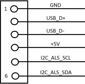
Knowing where the voltage rails are located is enough to work with.  If I was desperate I could use the same method for finding the rest of the pinout as I plan to use on the display connector – connect one pair at random, see if it enumerates, if not, reverse it, if it still doesn’t, swap for the other pair and repeat.  But I decided to cheat a bit and researched the Macbook schematics that I have to see if Apple had previously used a pinout with Ground, two skipped pins, then 5V.  I found the answer to this in the schematic for the Macbook Air A1370 LIO board – a pinout with GND as pin 1, 5V as pin 4, and two USB and two i2c pins:

A MSPaint rendering of the Macbook Air camera connector pinout.  I feel it unwise to post the actual schematic.  It's on the internet, go look for it if you're curious.

A MSPaint rendering of the Macbook Air camera connector pinout at the LIO board.  The actual schematic is available on the internet, go look for it if you’re curious.

This is very valuable information.  First of all, it notes that the pin numbering on this side of the board is different than the silkscreen on the Air board, placing GND as pin 1 instead of pin 6, etc.  Second, it makes the pinout (1-6) GND, USB_D+, USB_D-,+5V, I2C_SCL, I2C_SDA – this makes a lot of sense, as the pinout for normal USB connectors is +5/D-/D+/GND.

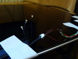
So without further ado, let’s see if this pinout is accurate.  I pulled the socket off of the Air board with my hot air station and wired it to a cut USB cable.

This wasn't much fun to solder.

This wasn’t much fun to solder.

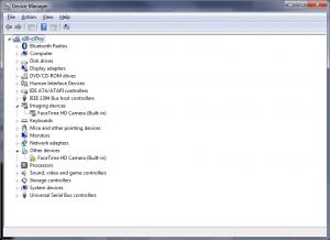
Now, when connected to the USB port, gasp!  New devices!

Holy cow, it's alive!

Holy cow, it’s alive!

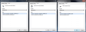
The camera enumerates as a USB Composite Device (USB\VID_05AC&PID_8510&REV_8025) with two sub-devices, both identified as “FaceTime HD Camera (Built-in)” (USB\VID_05AC&PID_8510&REV_8025&MI_00 and _02).  The _00 device installs automatically with generic Windows imaging device drivers; the _02 device claims no drivers could be found.  The solution is probably to dig through the BootCamp drivers and find one, but that’s a headache for another day.

The camera enumerates as these three devices.

The camera enumerates as these three devices.  Not sure why it finds drivers for one but not the other.  Nor, for that matter, why it’s two cameras…

But that doesn't matter because hooray, it works!

But despite the questions, hooray! It works!

So there you have it!  Camera operational, simple as that.  But what about the i2c connection?  What does it do?  The answer to that is in the schematic as well.  The netnames are “I2C_ALS_SCL” and “I2C_ALS_SDA”.  These are the communication bus for the Macbook Pro’s ambient light sensor.  I will leave the protocol hacking of the ALS for another post.

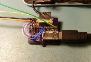
For those who wish to hack around with the camera and ALS, I have drawn up a simple breakout board with a camera connector, a mini-USB, and a 0.050″ header for the ALS.  I’ll post files for that board here as soon as I get a chance.  Remember though that I don’t have a source for the camera connector mate socket, so you’ll probably need to source a used camera board with the appropriate connector and harvest it.  The price is not bad; I paid about $6 for mine.

For a sense of scale, remember that that's a miniUSB...

For a sense of scale, remember that that’s a miniUSB…

That’s enough for this installment.  Next time, hopefully I’ll be showing off the working panel.

<< Previous post in this seriesNext post in this series >>

Hacking the iPad 3 LCD, A Simpler Approach Part 4: Kit Costs

A lot of people have been asking about how much these boards cost, so it seems worthwhile to post a little something to clear this up.

I’m not looking to make a huge profit of any of this.  Actually it just makes me happy that anyone is interested at all in what I’m doing.  So rather than keep my costs under wraps and provide you with a blackbox number, here is the actual amount that it costs me to build one of these boards, by component (in USD):

Component Vendor Vendor PN Cost ea Qty Ext Cost
PCB, MM PCB10002 REV B, Simple iPad Breakout OSH Park PCB10002 REV B 3.17 1 3.17
Connector, DisplayPort, SMD, Molex 0472720001 Digikey WM19271CT-ND 5.30 1 5.30
Connector, FFC, 51 Pos, 0.3mm Pitch, Molex 5022505191 Mouser 538-502250-5191 5.56 1 5.56
Capacitor, Alum Elec, 100uF, 10V, TH, Panasonic EEUFR1A101 Digikey P14373-ND 0.33 1 0.33
Diode, Schottky, dual common cathode, 25V, 1A, TO-261, NXP BAT120C,115 Digikey 568-6921-1-ND 0.77 1 0.77
LED, Green, SMD 0805, OSRAM LG R971-KN-1 Digikey 475-1410-1-ND 0.08 1 0.08
Resistor, 100 ohms, 1%, 1/10W, 0603, Yageo RC0603FR-07100RL Digikey 311-100HRCT-ND 0.10 1 0.10
Resistor, 100 ohms, 1%, 1/16W, 0402, Stackpole RMCF0402FT100R Digikey RMCF0402FT100RCT-ND 0.025 12 0.30
Resistor, 0 ohms, 0603, Yageo RC0603JR-070RL Digikey 311-0.0GRTR-ND 0.10 2 0.20
Total 15.81

Now, not all of these parts are used in the same buildup.  The diode and the 0 ohm resistors aren’t installed at the same time; the 0402 resistors aren’t installed at all if the board is to be used for a projector build as they’d be unnecessary, etc.  But I will kit all the boards based on this set of parts anyway, so this is the base cost for one unit.

There are additional ancillary costs not rolled into the above BOM.  Packaging costs (antistatic bag, padded envelope), pre-soldered wires (if desired), assembly materials (solder paste, flux remover, etc), assemble-it-yourself materials (stencil, if desired).  And you’ll note that I have not touched labor yet – if you want me to build up the boards, I will need to charge a nominal assembly fee.  I won’t charge you a fortune, but it would be foolish to work for free.

I have quotes out at stencil manufacturers and will query the usual shipping suspects for pricing this week ([EDIT 2013.08.08] Shipping to the continental US is typically $3 for one or two units, shipping international is averaging about $7).  The cost is $20 for a kit of parts, $30-$35 for an assembled board (pending stencil quote [EDIT 2013.07.09] None of the inexpensive stencil fabricators can do the aperture/web sizes on this board, so I’d need a professional stainless-steel stencil – which I won’t go for unless I get enough people interested in boards to offset the cost), plus shipping to your location.  Note that this isn’t a start-to-finish kit – you’ll still need to provide a stable 3.3V source (assuming your DisplayPort cable doesn’t do so), and a source of 19-20V if you want to drive the backlight.  This board was designed for the DIY projector crowd to be as cheap and simple as possible, so please be aware of its limitations.

I hope the projected cost isn’t more than expected.  Labor is going to be the thing that really drives the price – right now it takes me an hour or so to build a board since I’m applying paste by hand.  I hope that I can get a stencil done for a reasonable price to reduce that effort.  We’ll see.  Nope.

More on this later.  If you’re interested, please drop me a comment or an email so I can gauge interest.  If a hundred people want one, a $180 professional stencil suddenly isn’t quite so big a deal (this board is too complex for the most inexpensive prototype laser services).  Plus then quantity discounts start to apply on components and the BOM cost drops.  Which means cheaper boards for all!  Yay!

<< Previous post in this series

Hacking the Macbook Pro Retina LCD, Part 1.2: Controller Addendum

D’oh.

A shipment of components including the connectors intended for the Macbook LCD breakout board arrived yesterday.  I-PEX components are not carried at the usual US distributors, so I opted to order a TE part that a random source seemed to indicate might mate (5-2069716-2).  Well…
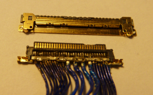
Well, that isn't going to work.

Well that isn’t going to work.

That’ll teach me for not doing my research.  The pin pitch isn’t even correct.  So I cost myself a few bucks and a week of time.  Damn it all.  But I have ordered a few genuine I-PEX Cabline-CA connectors on eBay, so in only another two weeks, I should have things figured out enough to spin a “proper” simple breakout.  The long leadtime of OSH Park is really killing me these days.

In the meantime, Daniel has sent me some more photos of his Samsung controller boards and has made great progress in his efforts.  The Samsung boards look like this:

Macbook Retina controller board, Samsung version - component side

Macbook Retina controller board, Samsung version – component side

Macbook Retina controller board, Samsung version - connector side

Macbook Retina controller board, Samsung version – connector side

His progress has compelled me to do a little additional work of my own – even though I swore I wouldn’t solder more jumpers to the panel.  Oh well, promises were meant to be broken.  In order to know where to stick wires, I have spent some time investigating the hardware that makes up the controller PCB.  The brain of the display is the ParadeTech DP635 LCD timing controller.  While the specification for this part is not freely available, ParadeTech sells several other Tcons, such as the DP628.  Here is a block diagram of the innards of that part:
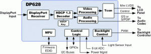
Block diagram for the ParadeTech DP628 DP Tcon.

Block diagram for the ParadeTech DP628 DP Tcon.

We will assume that the DP635 works sorta-similar.  From this, we can deduce that this IC takes in the DisplayPort signal and spits out something compatible with the chip-on-glass driver ICs on the panel.  In the ‘628 this is miniLVDS, and it’s reasonable to guess that this may be similar to the way it is done in the ‘635.  The backside of the controller PCB has pairs of testpoints labeled D1D1P/D1D1N, D1D2P/D1D2N through D9D1P/D9D1N, D9D2P/D9D2N, nine pairs of pairs in all.  Presumably this is eighteen differential pairs carrying the decoded video data as converted from the DisplayPort source.  As my panels are functional I will leave this as a theory and not pull off the IC to probe it out to the testpoints.

Speaking of testpoints, there are plenty of them.  Here’s a list of the marked points, primarily found on the connector side of the PCB:

  • D1D1P/D1D1N, D1D2P/D1D2N thru D9D1P/D9D1N, D9D2P/D9D2N (differential video channels, as noted above)
  • IVCC
  • IVCC28
  • IVCC18
  • IVCC12
  • VSYNC
  • CSCL
  • CSDA
  • TEST_EN
  • BIST
  • FSS
  • FLK24
  • VGL
  • GMA1 thru GMA14
  • LOCK_FB
  • VCOM_OUT
  • WP_PGMA
  • SCL_P
  • SDA_P
  • PVDD_O
  • PVDD_E
  • GCLK1 thru GCLK4
  • VDD
  • VST
  • DSC
  • VGH
  • SDA, SCL, WP_GND (near the EEPROM on the component side)

Some of these pins seem to be pretty self-explanatory (SDA/SCL/WP, for instance).  Also, the “IVCC” pins are obvious.  These pins indicate that there should be a 2.8V, a 1.8V, and a 1.2V rail.  Probing these pins did not immediately yield these results, which merits discussion.

In the previous post, I applied 3V to the panel, which I figured would be enough to activate the switching power supplies on it whether they were meant to run on 2.5V or 3.3V (the latter being extremely common, and the former starting to gain traction in newer panels).  It was unusual to find the panel fading to white.  Per the eDP specification, the panel should be continuously refreshed to black with no signal driving it, so something seemed to be wrong.

There appear to be around a half dozen voltage rails on this board.  Testpoints break out input voltage (point IVCC) as well as 2.8V (IVCC28), 1.8V (IVCC18), 1.2V (IVCC12), -6V (PVDD_O and PVDD_E) and 20V (VGH) (more on those two some other time).  But the 1.2V and 2.8V testpoints appeared inactive.  Both of these supplies appeared to be driven by mystery-chip GD=EC on top.  Thus, my immediate theory became that the DP635 relies on the 2.8V and/or 1.2V rail, and the fading to white is the (powered) LCD glass resetting as it is not being actively driven to black.  Why white I don’t quite understand yet since IPS is naturally black, but let’s ignore that for now.  I increased my input voltage to 3.3V at this point, which seemed to make no difference.

I began to suspect that GD=EC is a dual buck regulator, based on the testpoints underneath it and the general layout of the components.  I probed the components and ended up with a schematic that appeared to agree.  I noted before that I suspected the part was a Richtek regulator, which came to me when I found a teardown of another product which had a confirmed Richtek part with a similar marking.  Now armed with the fact that the part is a dual buck regulator, and that it comes in a 10-pin 3×3 DFN, this was enough to track it down – the part is a Richtek RT8035 (Datasheet).

From the datasheet’s pinout (which I had already mostly figured out from probing the surrounding components), I located the device’s Enable pins and noted that the voltage measured here with 3.3V provided by the source was around 1V, which according to the regulator datasheet is between the Enable and Disable voltage limits, which puts it somewhere in a possibly-undefined region of operation.  In fact, probing the outputs of the regulator showed that there were occasional pulses of voltage produced.

Well, if it was a 2.5V panel it wouldn’t have these problems at this voltage, so that idea was discarded.  If this is indeed a 3.3V panel, it should be safe to apply up to 3.6V or so.  So I applied 3.5V to the panel, and lo and behold, the panel turned black, the current draw increased, and upon testing all the supplies appeared to be online.

I did a little more investigation, since that seemed a strange operating voltage, and noted that I was actually losing quite a lot in my wiring.  Even the two feet of 22AWG I was using was dropping one or two tenths of a volt.  When compensated for that, the panel seemed to run on 3.3V – but only just barely.  It is hard to believe that it is actually a 3.3V panel, it seems to have almost no bottom-end voltage tolerance.  My rational side says the panel should easily run on something higher than 3.3 – maybe 5? – since all of its important circuitry appears to be powered on switching subregulators and not from the incoming VCC.  But I can’t bring myself to smoke an otherwise working panel, so for now I will set my supplies to 3.5V and call it good.  Plus DisplayPort runs on 3.3V and the pullups and pulldowns might use the input rail, so we don’t want to go too high.  For what it’s worth I have not seen any other Apple LCD product use a logic rail above 3.3V – not to say that it isn’t the case, but it would be uncommon.

So now the panel was running, drawing about 600mA at 3.3V (for what it’s worth, it only drew about 200mA when it was misbehaving and showing only white).  That’s about 2W of panel drive power, which sounds about right.  It might rise slightly when driven under certain circumstances.  Neat!  Let’s do something with it.

To go any farther, I’d have liked to use a breakout cable to avoid having to solder to the panel itself.  But what the hell, I’d already soldered on it a ton to remove the shields and to install some power and test jumpers, so what had I to lose.  Assuming from the block diagram of the DP628 (remember that?  I’ve rambled a lot since then!) that the DP635 takes in DisplayPort, and remembering from the DisplayPort specification that the DP lanes and AUX pins are capacitively coupled, and additionally that AUX and HPD have pullup or pulldown requirements, there will need to be a group of capacitors and resistors somewhere on the board that correspond to the requirements of the specification.  Suspiciously, next to the DP635 appears this formation of components:
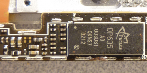
Ten capacitors and a handful of resistors, right next to the Tcon?  Iiiiinteresting.

Ten capacitors and a handful of resistors, right next to the Tcon? Iiiiinteresting.

The reference designators for these parts are listed off to the side – from top to bottom, left then right, the components are R47, R48, C75, C76, C77, C78, R49, then C69, C70, C71, C72, C73, and C74.  These are seriously small 0201 parts.  I noted in the last part of this writeup that I’d located the DisplayPort lane pins on the connector.  To confirm that these components are related to DisplayPort, I probed for continuity between here and the connector, and indeed they appear to be.  What’s more, R47 and R48 are 1Mohm resistors connected to capacitors C69 and C70; one resistor pulls to GND and one to VCC.  This precisely matches the description of the AUX channel.  Probing the center of the the series set, we can finally confirm that pin 11 on the I-PEX is AUX+, while pin 12 is AUX-.  Continuing in order, pin 14 connects to C71, pin 15 to C72, pin 17 to C75, pin 18 to C76, pin 20 to C77, pin 21 to C78, pin 23 to C73, and pin 24 to C74.  We still don’t know what order the lanes are in, but at least now we know the correct connection for AUX.

The advantage of knowing AUX is that now we can start connecting the panel to a PC and can see what Windows thinks of it.  By wiring the panel to a prototype of my Simple iPad Breakout (only for the DisplayPort connector) and shorting HPD to VCC, I got the panel to register as a 2880×1800 “Color LCD”:
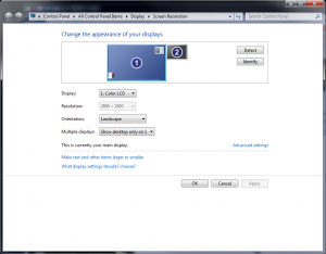
This is how the Macbook Pro Retina LCD registers to Windows.  This is a screenshot; the panel doesn't actually work yet since I don't have the lanes connected.

This is how the Macbook Pro Retina LCD registers to Windows. This is a screenshot; the panel doesn’t actually work yet since I don’t have the lanes connected.

Hooray, it’s alive!  When I was dealing with the white-screen issue I wondered if the damage to the PCB visible next to the DP635 had rendered the panel an expensive paperweight.  Now the effort is only figuring out the ordering of the lanes and the location of HPD, both issues which would be simple with a breakout.  For HPD, we need only measure which of the remaining unknown pins (9 and 10) goes logic high when voltage is applied.  For the lane ordering, there are only four probable orderings (0-/0+…3-/3+, 0+/0-…3+/3-, 3-/3+…0-/0+, 3+/3-…0+/0-), and with a breakout and jumper wires this should be found very quickly.

I got impatient and soldered in 36AWG magnet wire jumpers on all the lane lines, and tried a couple of the arrangements but have not yet been lucky enough to land on the correct one.  I’m not sure I’ll continue with this though – it’s massively frustrating, and I’m not even sure this panel is operational nor whether my soldering to the tiny capacitors makes a good connection.  It will take another two weeks, but I think I’ll just wait until I get in the corrected breakout boards to continue down this path.
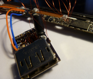
This was absolutely no fun to solder.

This was absolutely no fun to solder.

In the meantime I have been working on the backlight driver for the panel.  For the iPad panel, I used a Linear Technology LT3754 16-channel driver with integrated boost supply.  I like the concept of using drivers with internal boost supplies – one less IC to buy, and a decent savings of board area.  When you bump up from seven to sixteen series LEDs, the number of drivers that are capable of boosting to the necessary 51V or so internally is not quite so large.  The ‘3754 and its max 45V output is no longer usable.

I think for this panel I will be investigating the Freescale MC34844A.  This part is a 10-channel, 60V, 80mA/channel driver which can modulate based on analog input, PWM, or (interestingly) an I2C interface.  There exists a simpler 6-channel version of this chip, the MC34845, and I briefly considered using it, but despite the nicety of being a slightly simpler chip, the ’45 is Not Recommended for New Designs (is going end of life soon) so I dare not use it.  The only real downside of the MC34844A is that it only supports up to 28V input.  I’m a big proponent of hugely overdesigned voltage input overhead, because people do terrible things to electronics sometimes, and I liked the fact that the 3754 could work all the way up to 40V “just in case”.  So this version will only work to 24V, oh well.  I suspect most people would run it on 12V anyway so maybe I am needlessly cautious.  I already have parts for the new backlight driver, so as soon as I spin a board for it I can try everything out.

Holy cow, that’s a lot of words that don’t really have a lot of useful content.  I’m really feeling a setback since I built the first breakout around an incorrect connector.  But I’ve got the correct board in the works, and will order it on Monday, and hopefully by mid two weeks from now I’ll have a proper board and will have the panel running.  At least that’s the grand plan – I don’t guarantee I won’t screw up again… it’s a good thing OSH Park is so cheap!

In the meantime, off to work on the iPhone 4 LCD… stay tuned for that in a later episode.

<< Previous post in this seriesNext post in this series >>
Hacking the iPad 3 LCD, A Simpler Approach Part 3: Finished Design

The Revision B boards for the simple iPad Retina LCD breakout have arrived.  As I mentioned last time, this version fixes the mis-numbering of DisplayPort lanes that was present in Revision A.  A few additional tweaks were also made.  Take a look at the previous part for a more complete summary of the changes.

I have built up one board and tested everything out, and luckily this time everything seems to be working great.  Have a look:

Simple Breakout top side (bottom Gerber).

Simple Breakout top side (bottom Gerber).

Simple Breakout bottom side (top Gerber).  Ignore the flux - I am out of flux remover and didn't want to delay this post.

Simple Breakout bottom side (top Gerber). Ignore the flux – I am out of flux remover and didn’t want to delay this post.

Simple Breakout in action.  No longer are magnet wire jumpers needed, hooray!

Simple Breakout in action. No longer are magnet wire jumpers needed, hooray!

I noted in the comments for the previous part that I was attempting to etch stencils to speed assembly.  Using the method outlined here, I attempted about 20 times to reliably etch a stencil from a soda can, trying various transfer papers, heat/pressure application, and printer settings, and I never landed on a particularly reliable method.  The problem is that the pins on the connectors of this board are really small (FFC) or really close together (DisplayPort), and the ratio of depth to web thickness means it is very difficult to etch enough from all areas without overetching any others.  I finally landed on one that was halfway okay, but I still spent a lot of time pushing paste around with a toothpick.  If I knew I was going to have to build a few more of these, I’d definitely order a professionally-made stencil.

But now that this board is on the shelf, I need to shift my focus to the “real” iPad interface, which has more or less taken a backseat lately, so feel free to take this design and order your own, modify it to suit your needs, etc.  I also have some boards and stuff left over if you don’t want to buy your own directly (even though three boards is only $10 from OSH Park).  Shoot me an email or leave a message if you want something and we’ll see what we can work out.

I’ve re-linked the board documents here.  Do with them as you see fit.  Happy hacking!

<< Previous post in this seriesNext post in this series >>
Hacking the Macbook Pro Retina LCD, Part 1.1: Backlight Addendum

Wherein Mike is schooled by more seasoned hackers.

I don’t have enough for an additional full part to this series, but some information has been brought to my attention in regard to my findings in the last post and it’s useful enough that I have opted to write this addendum.

In the comments for the first part of this series, and in a followup email to the comments, fellow Retina display hacker Daniel Rozsnyo let me in on a clue regarding the backlight for the 15″ Macbook Retina panel.  The iFixit article notes 48 LEDs are present, which is correct.  But while writing the previous post I attempted to drive the backlight to test my pinout and gave it what I thought was more than sufficient voltage (up to about 35V) and… nothing.  Which made no sense – if indeed there were 48 LEDs, and they were in six sets, then there should have been 8 LEDs in series at 3.2V apiece for 25.6V required.  But nothing happened.

Daniel let me know via email that I was missing one essential piece of information: there are two LEDs in series in each package.  So while there are 48 LEDs, there are actually 96 dice, in series sets of sixteen, not eight.  Daniel sent me the following photo of the LED strip out of his panel, in which you can almost make out two dark spots in some of the devices – and at very least you can see that the white plastic cases are semi-divided in the middle.

LED strip out of the Macbook Retina panel (in this case the Samsung panel, but they seem to be very similar).

LED strip out of the Macbook Retina panel (in this case the Samsung panel, but they seem to be very similar).

I would never have come up with that without a little prodding, so thanks Daniel.  I have seen devices like these (Nichia and OSRAM make plenty of different models), but never with two series dice before.  The reason for using these unique devices may have been the desire for more even lighting across the display surface.  A reasonable amount of the linear space along the base of the panel is wasted in solder pads and device packaging, so stuffing two LEDs in each package halves the amount of overhead and allows the LEDs to be packed closer together, which reduces backlight banding.

With this new knowledge in hand, I soldered in some jumpers and applied about 46V to one of the strings through a 100R resistor and sure enough, it lit up.  IPS displays like this one are naturally black, however, so that wasn’t very exciting.  I also soldered in jumpers to apply V+ to the LCD controller (which I set at 3.0V, which should be within the range of both 2.5V and 3.3V panels – since remember I don’t know what the proper driving voltage for this panel is), and when V+ is applied, the panel slowly drifts to gray/white.  I am not yet sure whether this is good or bad, but in any case it allows us to look at the backlight dispersion pattern in a bit more detail.

The Macbook Pro Retina LCD assembly, with the panel plus one LED array powered.

The Macbook Pro Retina LCD assembly, with the panel plus one LED array powered.

I said this at the end of the last post, but I think I mean it this time: This will probably be the last I touch the display until I get my breakout boards in, which should be late next week.  I have contemplated soldering in bunches of tiny magnet wire flyouts and wiring the panel into my iPad test boards, but I don’t want to damage any more than I already have.

Which reminds me: I removed the EM shield frames from the controller, so now you can more easily see all the parts that may have been obscured before.  I also removed all the insulator stickers from the top side, revealing a bunch of labeled testpoints.  Enjoy! (Ignore the jumper wires, eh?)

Macbook_LCD_Controller_Front1 Macbook_LCD_Controller_Front2 Macbook_LCD_Controller_Front3Macbook_LCD_Controller_Back1 Macbook_LCD_Controller_Back2 Macbook_LCD_Controller_Back3

<< Previous post in this seriesNext post in this series >>