I’m a huge sucker when it comes to playing with shiny new tech, and straight from the shiny tech factory I’ve gotten ahold of a new toy which in terms of raw number of pixels puts the previous panels I’ve been working with to shame. Say hello to the Sharp LQ156D1JX01!

It’s pretty glossy. Look, a reflection of some of my test equipment!
The LQ156D1JX01 is a new inductee to the ultra-high-DPI panel club, whose members have lately found their way into many high-end gaming laptops and ultrabooks. This particular panel is a pull from a Toshiba Satellite P50T. The panel measures a whopping 3840×2160 pixels (that’s 4K, or 8.29 megapixels!) in a mere 15.6 inch size. Now, that doesn’t quite compare to the current generation of cell phones with 5-inch 4K screens, but at something like 282PPI it’s nothing to scoff at either. This pushes far above the 220PPI of the Macbook Pro Retina panel that we’ve played with before, and puts it somewhere between the 264PPI of the iPad 3 Retina panel and the 324PPI of the iPad Mini 2 Retina. Like the Macbook and the iPad, the LQ156D1JX01 runs on 4-lane Embedded DisplayPort. Where it differs a bit is that this panel is reportedly addressed as two 1920×2160 half-displays over DisplayPort 1.2’s Multi-Stream Transport. This may have been done to simplify timing requirements for such a massive display.
I don’t happen to have a proper connector on hand for this panel so I haven’t fired it up yet, but like any good engineer, before even bothering to plug in my new toy I went ahead and tore it apart. This was actually a necessary step, because there is currently no publicly-available datasheet for this panel, so we need to figure out the pinout of the connector in order to make it do anything anyway.
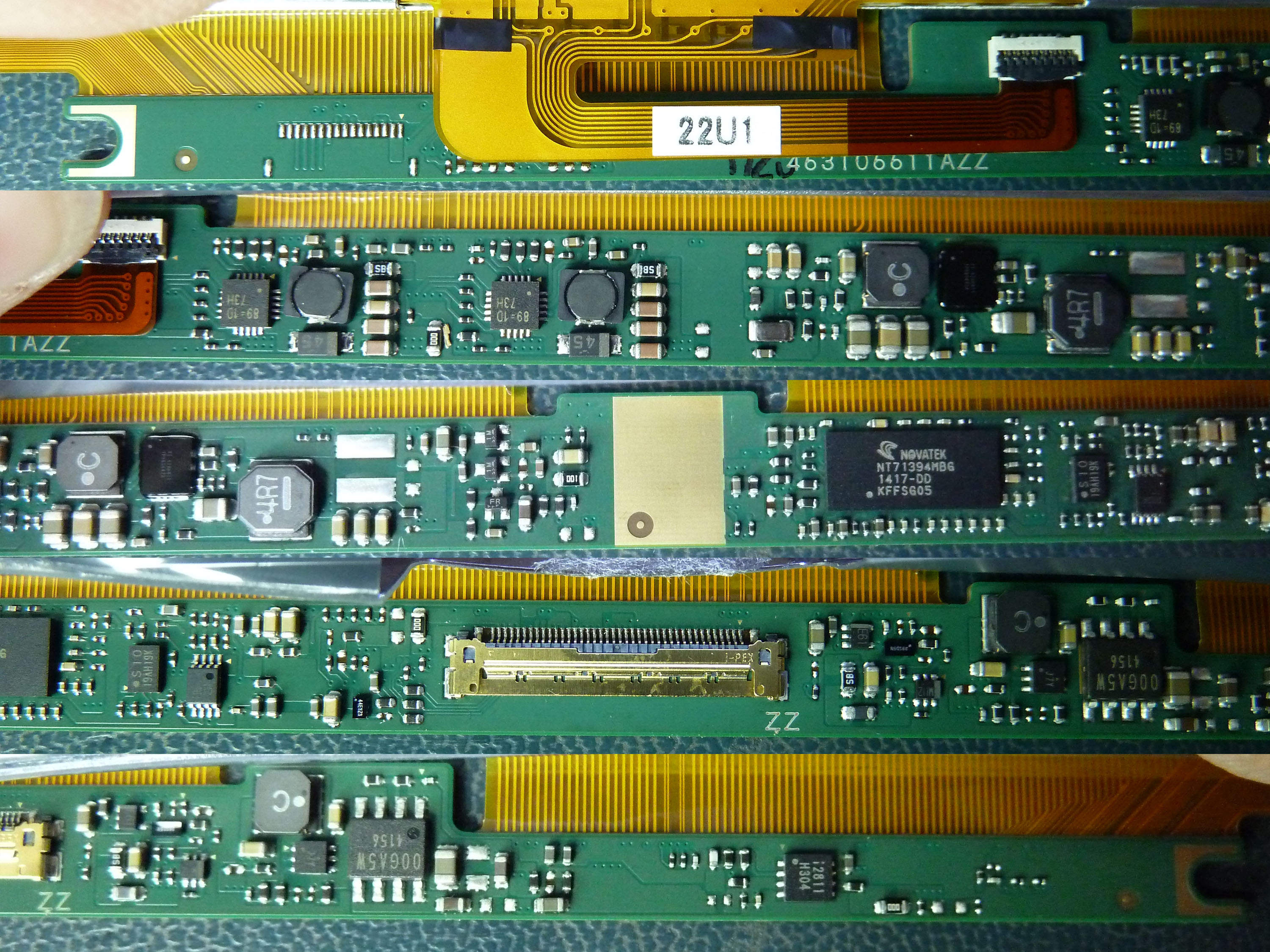
LQ156D1JX01 control PCB top side collage
Before delving into the pinout, we can find out several things about this panel by looking at the design of the control board. The main connector is made by Dai-ichi Seiko I-PEX and appears to be a 40-position CABLINE-CA series part, possibly 20525-040E-02 (pdf link). The panel is driven by a Novatek NT71394MBG. This part does not seem to have any publicly available information, but we’ll assume it’s a timing controller ASIC. There is a TI power management IC that appears to generate all the necessary panel voltages; I think it’s a TPS65642A (pdf link). There are also two chips marked 89=1D, these are Richtek RT8532 boost LED drivers (pdf link). The design of the backlight flex implies that each of these ICs drives four LED channels, despite being capable of six.
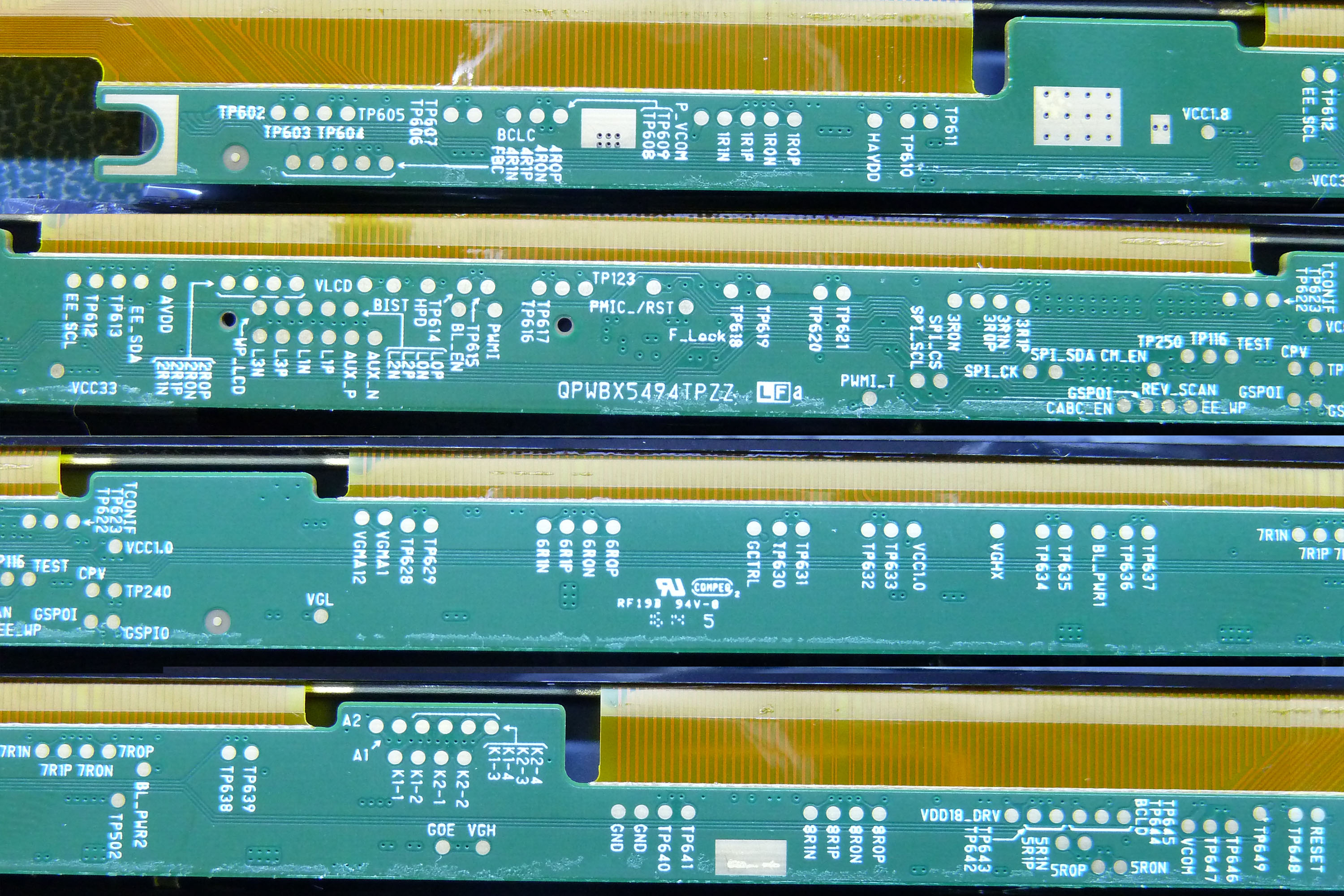
LQ156D1JX01 control PCB bottom side collage
Now that we have some idea of what’s going on in the panel, on to the pinout. Thanks to Sharp, this task is simple, because all of the pins are connected to convenient labeled testpoints on the bottom of the board. I haven’t tested the panel yet so I don’t know if this is 100% accurate, but as far as I can tell at this point, the pinout for the LQ156D1JX01 is as follows:
| Pin | Name | Description |
|---|---|---|
| 1 | PMIC_/RST | Power Management Reset, Active Low |
| 2 | GND | Ground (Shield) |
| 3 | L3N | Embedded DisplayPort Lane 3 Negative |
| 4 | L3P | Embedded DisplayPort Lane 3 Positive |
| 5 | GND | Ground (Shield) |
| 6 | L2N | Embedded DisplayPort Lane 2 Negative |
| 7 | L2P | Embedded DisplayPort Lane 2 Positive |
| 8 | GND | Ground (Shield) |
| 9 | L1N | Embedded DisplayPort Lane 1 Negative |
| 10 | L1P | Embedded DisplayPort Lane 1 Positive |
| 11 | GND | Ground (Shield) |
| 12 | L0N | Embedded DisplayPort Lane 0 Negative |
| 13 | L0P | Embedded DisplayPort Lane 0 Positive |
| 14 | GND | Ground (Shield) |
| 15 | AUX_P | Embedded DisplayPort Aux Channel Positive |
| 16 | AUX_N | Embedded DisplayPort Aux Channel Negative |
| 17 | GND | Ground (Shield) |
| 18 | VLCD | 3.3V LCD Power |
| 19 | VLCD | 3.3V LCD Power |
| 20 | VLCD | 3.3V LCD Power |
| 21 | VLCD | 3.3V LCD Power |
| 22 | BIST | Built In Self Test |
| 23 | GND | Ground (LCD Power) |
| 24 | GND | Ground (LCD Power) |
| 25 | GND | Ground (LCD Power) |
| 26 | GND | Ground (LCD Power) |
| 27 | HPD | Embedded DisplayPort Hot Plug Detect |
| 28 | GND | Ground (Backlight) |
| 29 | GND | Ground (Backlight) |
| 30 | GND | Ground (Backlight) |
| 31 | GND | Ground (Backlight) |
| 32 | BL_EN | Backlight Enable |
| 33 | PWMI | Backlight PWM |
| 34 | EE_SCL | EEPROM Clock (EDID?) |
| 35 | EE_SDA | EEPROM Data (EDID?) |
| 36 | BL_PWR1 | Backlight Power |
| 37 | BL_PWR1 | Backlight Power |
| 38 | BL_PWR1 | Backlight Power |
| 39 | BL_PWR1 | Backlight Power |
| 40 | WP_LCD | Write Protect? |
I have not marked the backlight voltage in the table, because I am not certain what the design voltage range is. RT8532 has an operating range from about 5V to 24V, but it is not currently known what the components in the display are actually rated for. My guess is it’s probably safe up to at least 12V, but try at your own risk.
It’s interesting to see EEPROM pins brought out. I suspect these are for the EDID EEPROM, maybe for factory programming of the device. Or maybe it’s something completely different. Again, without having fired up the panel, this is all speculation. There is an explicit “EE_WP” testpoint which is not the same as the “WP_LCD” that is brought out; I don’t have any good idea for what the latter may be used for.
So that’s about it. The next step is to wire up a connector and get the panel running, but that won’t happen today. Stay tuned for a followup post.
I’m impressed and relieved. Just as I was thinking that all hope for getting my hands on this panel’s datasheet is lost, you come to the rescue. I literally tried to contact every source (manufacturer, sellers and distributors) to no avail. Either no one had it or they sent me to the other one.
Bit of a bummer: that’s a MST, but I can definitely live with that.
I think that the connector type is listed at panelook (20525-040E-02, 0.4mm pitch I believe). If I remember correctly I was even able to find a socket on sale on aliexpress. Had no luck with the plug or a cable assembly tough.
Good luck Mike, keep it coming. I’m sure that I’m not the only one keeping my eye out on your developments ;).
Hey, thanks! I really wasn’t sure if I wanted to buy one, but then I found someone selling this one for $115 when everybody else wanted $300+ and I couldn’t resist. I figured if worse came to worst I could always re-sell it and get my $115 back. Of course that was before I peeled all the stickers off to get those photos of the PCB, so I’ve probably reduced its value somewhat 🙂
I updated the connector part number. I thought it was a -01 because as you can see in the bottom board images, there are non-plated holes which could have pegs in them (which would be the -01 option). But Panelook has the datasheet, so they probably know best.
Regarding MST, that’s a rumor I read, I haven’t verified that it’s true of course (since I haven’t powered up the panel). The source is this: http://lgponthemove.blogspot.com/2014/08/first-impressions-toshiba-satellite.html … I’m tempted to believe it, though, since the reviewer seems to have a competent technical understanding of the unit.
$115? May I ask where were you able to find at that price? Was it one-time deal/some guy selling single unit? I got a bit discouraged by the usual $300 price-point, but at that price it sounds much more manageable, provided it’s a working unit. All the places on the web, that I was able to find selling the panel offer awfully short warranty periods, so I’ll need to have everything in place to test one before ordering. I’m afraid that my budget can’t take a hit on a malfunctioning one at the moment. And then there’s the issue of getting a cable to hook it up or even attempt any kind of a break-out work. Sounds really basic, but for now a real show-stopper. If you manage to find it somewhere or try to gather some momentum for a whole-sell deal, please let us know Mike (preferably in an update or future post). I’ll do my best trying to find one on my own and keep you posted, but my experience in sourcing this kind of parts is rather limited.
It was a one-off eBay auction, yeah – a supposedly working pull from a laptop that was parted out. I got tipped off from a friendly fellow visitor to this site (Hi again Tim!). I could put together a group buy, but that doesn’t start to make good sense until you hit at least ten or twenty pieces, and I don’t know that there’s that many people interested just yet 🙂
If you want to pay through the nose for one, here’s a link to the cable from the source laptop of my panel: http://www.ebay.com/itm/251823183058?_trksid=p2060778.m1438.l2649&ssPageName=STRK%3AMEBIDX%3AIT … it might be ended by the time you read this, but it will probably get re-listed. I’d have bought one but I didn’t want to pay $45 for it.
Steep compared to what you got your panel for. Just to weight my options: what would be the best case scenario for a wholesale deal (per-piece)?
The rMBP assembly managed to gather some audience back in the day. And it looks rather bleak compared to this one. So here’s to popular demand!
For the cables, or the panels? I don’t know what panels would cost in quantity, I haven’t bothered to ask any vendors. I keep hearing costs on the cables being around USD$15 in reasonable quantities, plus or minus as much as $5 depending on particular vendor and the order quantity. Still not dirt cheap, but we’re not ordering thousands, and they’re being custom-made.
I do wish one of these bare panels would catch on more than the Macbook lid assembly – it’s difficult to integrate a Macbook lid into a finished product, the LCD itself can’t be separated from the lid assembly without damage, and even if you could, the bare unassembled panels don’t include the necessary backlight and rear films – it’s neat if you happen to already have one of the lid assemblies that you’d like to use instead of throwing it out, but if you want to create a polished product, it’s far from ideal.
I meant the cable. Paying over $40 for some bundle pulled from a laptop is quite a gamble. Who knows what’s on the other end of this spider web. Apart from that, it’s looks like a quite lengthy piece of a cable: I wouldn’t waste signal integrity on a panel-board connection alone.
As for the rMBP assembly, I didn’t mind that much that it was enclosed in the lid. In fact it made my life easier: I can’t imagine myself building a compelling enclosure for such a thing. The main issue that I had with it was the quality of the panel itself: both units that I had to work with suffered from a rather nasty case of image retention problem. And when I was ordering those via ebay, there was no way to tell whether I would get the LG or Samsung version of the screen.
Yeah, if I’m going to spend that much, it had better have a connector I can use on the other end, preferably one that doesn’t have a minimum 3000-piece reel order! (I’m looking at you, I-PEX)
I agree the lid assembly is convenient, if it’s workable as your final product, but a big Apple logo on the back of the part can be a little bit obtrusive depending on the application 🙂 It is these (well, technically the iPad) displays that actually pushed me over the edge to purchasing a milling machine, and now that it’s finally starting to be a reasonable temperature around here, I hope to spend some time machining proper aluminum desktop enclosures for some or all of my project displays. Too cold to do it in the dead of winter, my shop’s not heated!
This can be used for LQ156D1JX01 display 15.6 eDP 8-bit 40 pins 0.4mm pitch ipex 20525-040E-02 connectors
http://www.alibaba.com/product-detail/used-for-LQ156D1JX01-display-15-6_60218265851.html
I see that you posted some photos pcb board, is it the controller board of this LCD?
What’s the likelihood for the LCD to be used as a panel for a DIY LCD projector.
Really looking forward to reading your follow up report on this absolutely cool panel!
Yes, the photos I posted are of the controller board attached to the panel. What’s the likelihood of the panel to be used in a DIY projector? I guess just as much as any other panel of this size. Assuming there are no issues with driving it (yet to be seen), I don’t expect there to be any problems in removing the rear shielding and diffuser films. It is an awfully thin panel, so you’ll need to be careful with it once the supportive backing is removed. On the upside, since it’s an IGZO panel the brightness should be awesome (since IGZO is clearer than traditional a-Si).
It’s too bad it’s so damn hard to get ahold of compatible mate cables. I refuse to pay half what I paid for the panel for a stupid cable…
Yeah, the fact that it’s an IGZO panel is what makes it all the more special
I guess the only thing you need now to fire up the display is a matching eDP cable?
I don’t know if this will be helpful for you, but sometime ago I came across this seller, seemingly very active in promoting custom made eDP cables (and if I remember correctly, they’re also on alibaba and taobao as well),
A link to their site: http://www.lcd-cable.com/products_info/eDP-cable-20346-030-246620.html
Have you given them a try? I sure hope that they could provide you a solution
Another of Micro-Coaxial’s alter-egos, I see 🙂 Micro-coaxial.com, lcd-cable.com, lvds-cables.com, cables-oem.com, and a couple dozen Blogspot adverts, all the same company. “Jacky” sure knows how to get their name out.
Yes, I’ve contacted a branch of Micro-Coaxial about these sort of cables before. The answer I got was not bad per piece (~$15), but the minimum quantity was too hard to swallow (500pcs). Since then I’ve heard some quotes that other folks have gotten, and they don’t sound so bad. Although according to one report (Hi Tim!), Micro-Coaxial doesn’t stock the parts for this particular panel – the 40-pin Cabline-CA seems to not be a very common part.
I guess I need to get some more quotes.
Hi, Mike. Interesting project. Looks like I bought motherboard from this same laptop as You have this screen:) Now I`m trying to connect 1366×768 LCD on it. How do You think, are there any chances I could do this? For now looks like I got all the data lanes in place, but no signals. Could it be because motherboard refuses to send signals due eedid data? What signals, in Your opinion should come/leave PMIC_/RST, BIST, HPD pins?
Ah! HPD is important – by toggling HPD, the panel announces to the computer that it is there and ready for video. You’ll want to connect that one; your new panel should have a HPD output. The remaining two pins should be no-connect. I find it somewhat hard to believe that the EDID would be causing problems.
If you continue to have trouble, consider posting the part number of your panel, and I can take a look to see if there are any obvious compatibility problems.
I just realized, that my panel is LDVS, while motherboard uses display port:) I am new in electronics and do many mistakes. I tried to connect LP156WH3, datasheet is available at:
http://www.globalresell.com/datasheet/LP156WH3-TLS2_652.html
I also got original cable from that screen now, it seems like You are right about pin-out Mike. Grounds, powers are in place, in the original cable PMIC_/RST, BIST, EE_SCL, EE_SDA, WP_LCD are not connected to the motherboard.
I also have a question. This display uses for lines, how likely to work would be lover resolution display with two lines?
I kind of suspected as much… I almost pointed out that it’s fairly rare to find a 1366×768 panel that doesn’t use LVDS 🙂
LP156WH3-TLS2 takes 1-channel, 3-lane LVDS. If you connect it to a 4-lane source, you will either be missing the two most significant or the two least significant bits of each color, depending on the bit packing of the source (VESA or JEIDA). So either you’ll have a distorted display (most significant), or it’ll work just fine (least significant). 50-50 shot 🙂 In either case the resolution will be unaffected.
Most “universal” LVDS sources have the ability to set the bit packing and/or channel arrangement… of course if you’re connecting to a laptop, you probably won’t have that option. And certainly not with the P50t motherboard, which won’t drive a LVDS monitor without some sort of conversion (ex. NXP PTN3460).
Would this motherboard by compatible with B156HTN03? Datasheet is avalible at http://www.datasheetspdf.com/datasheet/B156HTN03.0.html Thanks for Your help, I probably would have fryed that motherboard already without this blog:)
“Probably.” As part of the DisplayPort handshaking and link initialization process, the source and sink are supposed to negotiate the number of lanes to use, so strictly judging by the specification, the fact that B156HTN03 has two lanes of input and the motherboard has four lanes of output shouldn’t be a deal-breaker. This of course doesn’t guarantee that Toshiba (or whatever ODM designed their board) hasn’t done something stupid and is forcing a particular lane configuration, etc.
The one slightly cautionary area is the backlight voltage; the B156HTN03 has a maximum backlight voltage of 21V whereas the original panel for that board could have taken 25V or so; if for some reason the motherboard uses the very top end of the voltage range, the backlight driver in the new panel could be damaged. I don’t think this is particularly likely, but you never know.
Other than that, of course the pinouts are different so you’ll need to figure out a harness to go between the two, but once you get past that, there’s a fairly good chance they should work together. Probably.
According to datasheet, backlight is rated from 7V (min) to 12V (typ) to 21V (max).
PWM period should be 200Hz typ, with 150Hz min and 2MHz max.
Your pinout is correct.
I2C is for panel EDID eeprom as you suspected.
WP is for the said EEPROM’s WP pin. Normally all that stuff is NC.
Not sure where you see MST stuff, the panel is SST. Which is nice.
I wonder why Sharp chose cabline-ca for the connector. Such rage.
Luckily, this 40pin eDP pinout seems to be standard across a few current 4K panels in this size, so matter of using them is just getting an appropriate cable made.
Thanks for the info! I think you’ll find that the PWM frequency range is from 150Hz to 2kHz though, not 2MHz.
The WP pin, I’m still suspicious of that. As I said in the article, there is an explicit “EE_WP” testpoint, and it and “LCD_WP” are not electrically connected. I suppose I need to probe around some more, because admittedly EEPROM Write Protect makes a lot more sense to be located on an external connector than anything else I can think of.
The MST note I read in this review: http://forum.notebookreview.com/threads/np9377-s-120hz-screen-replacement.763972/ … I’m not sure if it’s true or not. I still haven’t powered up my panel.
I do wish the standard was something from Hirose or JST or somebody similar… somebody that has distribution in the US. But I guess for Sharp, being a Japanese company, the availability of connectors from Dai-Ichi Seiko I-PEX (also a Japanese company) is much better. I at least hope with these panels becoming more prevalent, the connectors will begin leaking into the normal retail channels (eBay, Alibaba, etc) where we hobbyists can get to them.
I own a P50t-B and the screen is awesome.
Is it possible that the EEPROM is used to store LUT since this particular laptop model provides factory screen calibration? I haven’t figured out where it is stored yet.
I can buy testing cables for LQ156D1JX01, but I don’t know how to connect the following three pins,
PMIC_ / RST
WP_LCD
BL_EN,
If the three pins and BIST, EE_SCL EE_SDA don’t need connection, I want to buy screen and cable to experiment, if successful,it must be exciting.
Please tell me how to connect them, thank you very much.
BL_EN is important, it’s an active-high 3.3V logic signal that tells the backlight to turn on. PMIC_/RST and WP_LCD should not be connected.
I can buy cables, but I’m not sure how to connection some pins. If, as Julius says, several pins can be disconnected, things would be easier. How do I connect 32 BL_EN? it can be directly connected to the 3.3V DC electricity?
Yes, it’s a simple 3.3V logic signal, active high.
Any progress?
I’m looking to make a 4k rear projection tv, I was originally looking at the macbook retina display (they can be had for under $100). But this would be better, being higher resolution and IGZO so it’d be brighter (something I’m concerned about)
This monitor would be an ideal candidate.
Though I haven’t bean able to find any on eBay.
Yeah, I got lucky I think. There are plenty out there, but they usually run $300 or more. I haven’t made any more progress though, unfortunately…
Hi mike,
Any ideas on a multi monitor iPad min retina (the 2048×1536) with 326ppi?
I would like to attempt a multi monitor setup using 12 of the LG LP079QX1 panels( hoping to achieve a 16:9 aspect ration when tiled). Here is a controller supplier for them
http://abusemark.com/store/index.php?main_page=product_info&cPath=3&products_id=53&zenid=l83h66mb43rhdpgsmig4g5rq12
The supplier is in Japan and has oddly limited to 2 pieces …I live in the UK and was hopping for more options ….
How would one implement a digiteser to work over the whole tiled display of 4×3 iPad mini retina panels?
Hmm. Well, of the various types of digitizers out there, probably the cheapest to make at home for a reasonable cost will be infrared. A line of narrow lens infrared LEDs along two edges, a row of IR receivers along the opposite two edges, and a processor to scan through the array and determine where the beam is broken, simple. But it’s not perfect – resolution is limited by how closely you can space the detectors (certainly not close enough to do the resolution of the panels justice), and simple X-Y arrays like this have problems with multi-touch masking (two diagonal fingers is indistinguishable from four fingers in a rectangle).
So what other touch panel technologies do we have? Resistive, consisting of a sheet of glass and a sheet of plastic with resistive inner surface coatings, separated by a very thin insulator – press on the surface, the plastic flexes and the two sheets contact, and position can be deduced by the voltage divider formed. But then you need to find suitable sheets of plastic and glass and figure out some way to evenly coat them in a transparent resistive coating – somewhat difficult for the hobbyist.
There’s also capacitive – now one sheet of glass, but intricate conductive patterning applied, with position sensed by electric field fluctuations at the touch points. Again, no fun to DIY, especially in large scale.
There’s a few other ones out there too – Surface Acoustic Wave, which applies an ultrasonic wave to the screen surface and measures how the transmitted wave is reflected or absorbed by an incident object… And of course the standard Wacom RF-style digitizer. I don’t know enough about the former to know how difficult it would be to implement, but I assume it won’t be simple. And of course the latter doesn’t work with fingers, so it isn’t really valid here.
So if you can’t make one, what about buying one? Well, a 16×9 array is approximately 4 panels wide by 3 high, which makes almost a 30 inch equivalent display size – even commercial 30-inch digitizers are kind of rare, and certainly not cheap. So, I’m not sure what to tell you except… sounds like a fun project, and good luck!
OK, after 4 RMA attempts with ASUS, I finally got a board that worked.
When the system powers up, the back light power bus is stable at 12v, but the panel does not power up.
The VLCD has a pulse of 3.3v, but quickly falls to 0v. If I test the power at the connector, the voltage goes to 3.3v then more slowly discharges (as if through a large capacitor) to 0v. If I remove my DMM leads while it is discharging, the voltage holds there until I reconnect them.
So here are some questions:
1. what voltage should the BL_EN and PWM pins be brought to for a high signal? are they 3.3V?
2. will the back light function without VLCD power?
3. what could be causing the odd behavior?
4. Can I just wire in my own 3.3v supply?
Thanks
Tim
And, In a genius fashion, I jumpered BLKT_EN to BL_PWR1. I was trying to force-enable the panel backlight. It looks like beacuse that pin goes back to the Intel PCH, which is not rated for 12v, so something is going to need repair for sure.
We have illumination! I got tired of messing with the motherboard, and went ahead and powered up the panel through the test points.
Here are pictures:
https://drive.google.com/folderview?id=0B4ncak83gVoORXZBZnJQbFQzWU0&usp=sharing
For some reason the panel needs VLCD in order for the backlight to turn on. I’m not sure why. (perhaps the ASIC has control interfaces for backlight?)
I tested with 3.3v on VLCD, and 12v for the backlight drivers.
The panel did not seem very bright, considering the PWM was tied high (100% duty cycle). This could be due to the high pixel density.
As soon as I find a working motherboard, I will try to get video as well.
Thanks!
Tim
OK, I have made progress! Under Ubuntu (I could not get win8 to work, but thats probably a driver thing) I can boot the Q87T and it is detected as a monitor with the proper resolution. I can control the back-light through the buttons (Ubuntu shows brightness slider as well).
The issue is there is no video… With the “read-EDID” Ubuntu package, I can capture the folowing:
Checksum Correct
Section "Monitor"
Identifier "LQ156D1JX01"
ModelName "LQ156D1JX01"
VendorName "SHP"
# Monitor Manufactured week 5 of 2014
# EDID version 1.4
# Digital Display
DisplaySize 350 190
Gamma 2.20
Option "DPMS" "false"
Modeline "Mode 0" 533.25 3840 3888 3920 4000 2160 2163 2168 2222 -hsync -vsync
EndSection
The utility also reports:
<code
1 potential busses found: 7
256-byte EDID successfully retrieved from i2c bus 7
Looks like i2c was successful. Have a good day.
This could be the real i2C port (EEPROM_SDA/SCL), or it could be i2C-over-AUX. I will try to check which.
Any Ideas on the issue?
Thanks
Tim
The xrandr utility reports the following:
Screen 0: minimum 8 x 8, current 2560 x 1024, maximum 32767 x 32767
eDP1 connected primary 1280x1024+0+0 (normal left inverted right x axis y axis) 346mm x 194mm
3840x2160 60.0 +
2048x1536 60.0
1920x1440 60.0
1856x1392 60.0
1792x1344 60.0
1920x1200 60.0
1920x1080 59.9
1600x1200 60.0
1680x1050 60.0 59.9
1600x1024 60.2
1400x1050 60.0
1280x1024 60.0*
1440x900 59.9
1280x960 60.0
1360x768 59.8 60.0
1152x864 60.0
1024x768 60.0
800x600 60.3 56.2
640x480 59.9
This leads me to think the DP lanes (AUX at least) are somewhat initializing. I don’t believe the board is doing anything with the hard-wired I2c connection.
I bit the bullet and bought one of the P50t harnesses from the seller I bought the panel from. I just got it yesterday so I haven’t had much time to play, but I too have power and backlight but no display. The mate connector is a 30-pin Starconn part that mates with TE’s LCEDI series (which I coincidentally had around from a previous accidental purchase, hooray!). Of the 30 pins:
– 11 are DisplayPort (5 pair + HPD)
– 5 are backlight (3 power, 2 control)
– 4 are VCC
– 9 are GND
– 1 appears to be NC
So no, the display doesn’t appear to need any of the other connections. My testbench PC seems to be okay with the panel at boot (albeit with no display) and then claims link errors when it is plugged in subsequently, so I suspect my lane ordering is off somehow.
I’ll write an update post someday soon.
After spending my day scratching my head, I decided to photograph some old monitor panels I had lying around to rack up some coins on panelook.com. Long story short…. I GOT DATASHEETS!
https://drive.google.com/file/d/0B4ncak83gVoOQ2h2TXptaDJObTQ/view?usp=sharing
Your initial pin-out chart looks to be correct.
BTW: If you want to sanity-check that your panel is still functional, just jumper the BIST test point to the adjacent VLCD and it will enter a BLACK-WHITE-RED-GREEN-BLUE Loop.
Awesome! Would you mind if I hosted a copy of the datasheet on this site?
Of course not, its all yours! I will throw it in some databases too.
I think I may have figured out why my panel is not working. It looks like the cable was built incorrectly. Pin1 and 2 apear to be swapped, and there could be others. If the PMIC_/Reset is being shorted to ground, I bet that could cause the panel to not respond.
What do you think?
I don’t think so. If PMIC_/Reset were grounded, you wouldn’t be able to trigger the selftest. Plus my panel behaves the same way, and I have verified that my cable does not connect that pin to anything.
I’ve got bad news for you guys.
This panel will not work with PC.
I have it connected to a realtek UHD evaluation board (http://i.imgur.com/VfVoyZK.jpg) with my adapter (the green PCB in bottom center, which makes DP>40pin connector for it.
I think the issue is its a real eDP panel, and probably requires ASSR (which is eDP thing), and fails without it. The realtek firmware is made by vendor and I’m asking them if they’re enabling ASSR for DP, but my guess is that’s the problem.
I have a displayport generator I need to hookup to verify this, but for now that’s my findings.
I’m not sure if I agree that ASSR makes sense as the culprit here. ASSR being a content-protection scheme, I would expect that it would be preferentially enabled on the source side, not mandated by the sink side. That said, I don’t have any better ideas yet.
Well this is unfortunate…. No one has been able to make this work? I wired up a displayport plug and still nothing, so that somewhat rules out the PMIC Reset issue.
I’m also not sure I understand the issue of the ASSR thing. I’m driving it directly from an Intel CPU, through an EDP port, why would it not be the same as the laptop it was originally used in?
I also failed. It is only recognised as LQ156D1JX01 but doesn’t work, when I insert the dp plug into one of ports of videocard. The information about failure tells me that there are some problems with dp link and it can’t work with high resolution.
Some companies show they can make it work on TaoBao, I am not sure if it’s true. I have wasted some money and time.
Hello, it seems you all are really close. Has anyone tried getting the schematic for say Toshiba Satellite P50T, one that Mike got his LCD from? I see a motherboard for P50T on sale at eBay: http://www.ebay.com/itm/251876805557 Though steep in price; may be someone reading this blog would fetch it.
The screen of IPAD Pro is 12.9 inch,the resolution is 2732 x 2048,I love it’s size and resolution. Can it be connect to DP port of computer? Is it EDP interface? Who has the specification? I hope somebody can assemble it successfully.
Hi Mike! Quite an adventure here.
Question: do you still have your Sharp LQ156D1JX01?…
I’ve one Toshiba P50T yearning and in need of a replacement display.
If anyone here has one leftover that’s still working I’d like to purchase it!
I still have my panel, but I haven’t gotten it to work properly yet… I’m not ready to give up yet though, so it’s currently not for sale 🙂
Any news on this project? I still have not had any progress, still not video output.
Also there are just so many 4K screens out there now that I’m not sure if there is much of a point.
Oy… A busy end of year meant I actually haven’t touched it for months! I keep intending to get back to it, but it’s kind of low on the priorities list at the moment…
Well, It looks this project may have become obsolete
http://stores.ebay.com/ElecRealm/How-to-drive-the-3K-4K-5K-LCD-panel.html
At the point where you can verify that the DP interface works for those panels I wonder what could have been the issue with ours?
FYI whoever was looking for replacements for their P50T, there are now some on ebay.
I will hang onto mine for now but I might get the above to mess around with. Reverse engineer the dimmer etc.
Is there any way to drive such panels and use them as External Monitors via DP/ mDP? or even HDMI?