Monthly Archives: June 2013

Hacking the Macbook Pro Retina LCD, Part 1.1: Backlight Addendum

Wherein Mike is schooled by more seasoned hackers.

I don’t have enough for an additional full part to this series, but some information has been brought to my attention in regard to my findings in the last post and it’s useful enough that I have opted to write this addendum.

In the comments for the first part of this series, and in a followup email to the comments, fellow Retina display hacker Daniel Rozsnyo let me in on a clue regarding the backlight for the 15″ Macbook Retina panel.  The iFixit article notes 48 LEDs are present, which is correct.  But while writing the previous post I attempted to drive the backlight to test my pinout and gave it what I thought was more than sufficient voltage (up to about 35V) and… nothing.  Which made no sense – if indeed there were 48 LEDs, and they were in six sets, then there should have been 8 LEDs in series at 3.2V apiece for 25.6V required.  But nothing happened.

Daniel let me know via email that I was missing one essential piece of information: there are two LEDs in series in each package.  So while there are 48 LEDs, there are actually 96 dice, in series sets of sixteen, not eight.  Daniel sent me the following photo of the LED strip out of his panel, in which you can almost make out two dark spots in some of the devices – and at very least you can see that the white plastic cases are semi-divided in the middle.

LED strip out of the Macbook Retina panel (in this case the Samsung panel, but they seem to be very similar).

LED strip out of the Macbook Retina panel (in this case the Samsung panel, but they seem to be very similar).

I would never have come up with that without a little prodding, so thanks Daniel.  I have seen devices like these (Nichia and OSRAM make plenty of different models), but never with two series dice before.  The reason for using these unique devices may have been the desire for more even lighting across the display surface.  A reasonable amount of the linear space along the base of the panel is wasted in solder pads and device packaging, so stuffing two LEDs in each package halves the amount of overhead and allows the LEDs to be packed closer together, which reduces backlight banding.

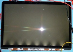
With this new knowledge in hand, I soldered in some jumpers and applied about 46V to one of the strings through a 100R resistor and sure enough, it lit up.  IPS displays like this one are naturally black, however, so that wasn’t very exciting.  I also soldered in jumpers to apply V+ to the LCD controller (which I set at 3.0V, which should be within the range of both 2.5V and 3.3V panels – since remember I don’t know what the proper driving voltage for this panel is), and when V+ is applied, the panel slowly drifts to gray/white.  I am not yet sure whether this is good or bad, but in any case it allows us to look at the backlight dispersion pattern in a bit more detail.

The Macbook Pro Retina LCD assembly, with the panel plus one LED array powered.

The Macbook Pro Retina LCD assembly, with the panel plus one LED array powered.

I said this at the end of the last post, but I think I mean it this time: This will probably be the last I touch the display until I get my breakout boards in, which should be late next week.  I have contemplated soldering in bunches of tiny magnet wire flyouts and wiring the panel into my iPad test boards, but I don’t want to damage any more than I already have.

Which reminds me: I removed the EM shield frames from the controller, so now you can more easily see all the parts that may have been obscured before.  I also removed all the insulator stickers from the top side, revealing a bunch of labeled testpoints.  Enjoy! (Ignore the jumper wires, eh?)

Macbook_LCD_Controller_Front1 Macbook_LCD_Controller_Front2 Macbook_LCD_Controller_Front3Macbook_LCD_Controller_Back1 Macbook_LCD_Controller_Back2 Macbook_LCD_Controller_Back3

<< Previous post in this seriesNext post in this series >>

Hacking the Macbook Pro Retina LCD, Part 1: First Looks

Since starting work on the iPad 3 LCD, I have become fascinated with Retina displays.  It’s crazy that you can pick up a panel that would until recently have cost hundreds or thousands for 60 bucks.  Mass production is a beautiful thing sometimes.  I may not be a Mac, but Apple gets my thanks for dragging the market out of the 1080p rut.

The only major issue with the iPad display is it’s less than ten inches diagonal.  That’s very small for everyday use.  They’re a nice portable size, but they’d look silly sitting on your desk as your primary monitor.  Of course Apple makes a couple more Retina products which are better suited to everyday use.  The largest of these is the display from the 15″ Macbook Pro Retina.

I believe my panel is from a Late 2012 Macbook Pro Retina 15″ unit. It is the LG version, model number LP154WT1(SJ)(A1).  I bought two of them on eBay for pretty cheap as semi-damaged top assembly pulls from complete laptops.  I ordered them about a week apart so only the first one has yet arrived.  The unit arrived with a screwdriver crunch in the controller PCB and the internal copper planes are visible, so hopefully it works without shorting.  Also the righthand cables were cut and there are two 3/8″ long quite deep scratches in one area.  Well, I guess you get what you pay for.

First looks
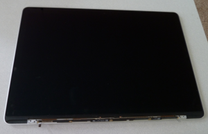
Macbook LCD assembly.

Macbook Pro 15″ Retina LCD assembly.

This really is a neat looking display.  The glass spans practically edge to edge (although the active area is around a half inch inset inside that, more on top to accomodate the camera).  According to the iFixit teardown, this assembly is only 7mm thick in the center with a panel glass thickness of 1.5mm.  That’s mighty tiny, but also not as impressive as it at first sounds as the bare glass doesn’t include the backlight and diffuser that a normal LCD has – that’s part of the full display assembly.  This is very important to note if you take up this project by purchasing one of the myriad bare-panel units on eBay – you’ll need to supply your own backlight, polarizer films and diffusers.  This can get quite pricey and/or labor intensive.

The bottom of the LCD houses a black PCB which most people identify as an inverter, but this is in actuality the LCD control electronics and has no control over the backlight (more on this later).  Inverter, in this case, is a misnomer anyway since the backlight is LED, and inverter topology backlight drivers are only applicable to CCFLs.  But I digress.

The top of the LCD controller board is very sparse.  Normally the WiFi/Bluetooth antenna array would be screwed to the top of this, so its lack of components was likely planned in order to prevent mechanical interference.  What are present are two connectors, labeled CNT1 and CNT2.
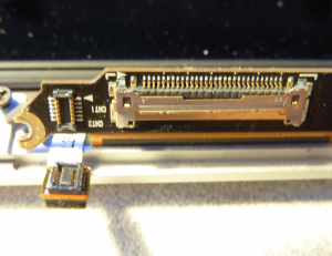
Connectors on the Macbook LCD assembly.

Connectors on the Macbook LCD assembly.

CNT2 is a 12-position dual row 0.4mm pitch board-to-board mezzanine connector with approximately 0.8mm stack height.  I can’t seem to find the exact connector, but they are similar to Molex SlimStack connectors. CNT1 is the main LCD power and data connector, and is a 30-pin I-PEX Cabline connector.

The LCD controller is held in place by a screw at either end and two adhesive pads in the middle.  In a complete assembly it would also be held in place by several additional screws which also affix the antenna array and the hinge cover, but these components were not present in the unit I purchased.  Removing the screws and unsticking the adhesive pads, the guts of the controller are revealed.  There are two metal shields covering the majority of the circuitry.
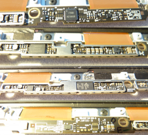
Detail of the backside of the Macbook LCD PCB.

Detail of the backside of the Macbook LCD PCB.  The metal shield covers have been removed.

Some of the ICs that are found:

  • Parade Technologies DP635 LCD Timing Controller
  • Integrated Memory Logic IML9660 Programmable LCD Calibrator
  • Silicon Mitus SM4031 Display Power Management IC
  • GD=EC 71L, 10-lead 3x3mm DFN (I believe this to be a Richtek DC-DC converter though I can’t yet prove it Proved it, it’s a Richtek RT8035)
  • 416R 8215, 8-lead 2x3mm DFN (I currently believe this to be an i2c EEPROM; there are SCL/SDA and WP testpoints nearby)

Naturally none of these things have datasheets available (EDIT: except for the RT8035!), but that’s okay, we really shouldn’t need them.  This should be a self-sufficient display unit, which we should be able to feed power and DisplayPort to and it should just work with no further investigation.  Hopefully.

Reverse-engineering the connectors

Unlike the iPad, I have been unable to locate a schematic for the Macbook Pro that explains the pinout of the connector.  But from looking at how the iPad connector is built, and from investigating some more prominent features of the panel with a multimeter and a keen eye, it is possible to get quite far in the determination of the pinout.

Let’s begin with connector CNT2.  We know that CNT2 goes to the display’s single backlight LED array from the iFixit teardown.  This also tells us that there are 48 white LEDs in the array.  This will become relevant in a moment.

On the main PCB, suspiciously nearby behind CNT2, is a 1206 ceramic capacitor, C103 (around 1.8-2.2uF, measured at 1.9uF).  A bit of probing tells us that one end of the capacitor is tied to the gold-plated mounting pads for the screws, which is bound to be GND.  The other end is tied to pins 5 and 6 (assuming pin 1 in upper right and pins numbered 1-6 top to bottom on right, 7-12 on left).  Thus we can assume that pins 5 and 6 are the anode(s) of the LED array.  More probing reveals that the two pins are also tied together in the mate connector, so we will assume that it is a single anode design.

Remember there are 48 LEDs in the array.  The vast majority of LED drivers can only drive arrays that have equal numbers of LEDs in them.  There are 10 remaining unknown pins on the backlight connector, but this is not an even divisor of 48.  It is therefore quite likely for some of the pins to be no-connects, and for the LEDs to be split into series strings of 48, 24, 16, 12, 8, or 6 LEDs depending on the number of cathode connections present.  It is difficult to determine the cathode connections at this point, so we change focus.

Let’s take a look at CNT1.  We can assume that if this display is in fact eDP as everyone says, this connector is required to have the following:

  • 4 lanes / 8 pins DisplayPort data (high resolution displays such as this will use all 4 lanes)
  • 2 pins Aux channel
  • 1 pin Hot Plug Detect
  • At least one +V pin (probably several)
  • At least one ground (probably several)
  • Backlight control – either:
    • anode and cathode connections from an off-board LED driver, or
    • PWM, power and enable signals for an on-board LED driver

As a shot in the dark, I probed the connector to determine whether it happened to contain connections to the LED anodes as previously discovered, and sure enough, pin 1 was connected.  Followup probing revealed that pins 3-8 were connected to pins 12-7 of CNT2.  So it is apparent that the backlight driver for this panel is housed off-board, and that there are six driven strings that make up the backlight.  This means there are 8 white LEDs per string, and if they consume around 3.2-3.4V apiece (common for white LEDs), the strings need to be driven with 25.6-27.2V each.  We’ll file this knowledge away for a while.

We know that the mount/screw pads should always be GND, so this is where we turn next.  Probing the connector for continuity to a mount pad, we find that pins 13, 16, 19, 22, 25, 26, and 27 are GND.  This arrangement provides some further insight:  There are three GND pads at the righthand side, which are likely the main power GND connections.  Also every third pad is a GND for a long period.  It is very common to separate high-speed signal lines with a GND connection, so we can guess that the four DisplayPort lanes can be found between the remaining GNDs.  We’ll confirm that in a moment.

We now know where power GND is located, and there are three unknown pads adjacent which are very likely to be +V.  This can be verified easily, as there is a 3A/32V fuse (F1) on the rear of the panel.  As there are no other fuses present nearby, we can assume that this is the fuse for the power input, and measuring continuity between it and the connector yields that much as expected, the last three pins (28, 29, and 30) are +V.  We don’t have a way of knowing yet how much +V is, but at least we know where it is.

It is assumed that pins 14-15, 17-18, 20-21, and 23-24 are the DisplayPort lanes, but we don’t know for sure.  For this, I unwrapped one end of the I-PEX cable that runs through the hinge to look at how the wires were arranged.  A twisted pair or coaxial line would certainly mean high-speed data.  As predicted, removing the (very well adhered) black adhesive cloth and desoldering some of the connector casing revealed four coaxial pairs on the pins in question.  The connector also showed that the righthand pin of each pair has an insulated coating whereas the lefthand does not.  I arbitrarily assume that the insulated wire is data+, and the uninsulated is data-, but verification of this is needed.
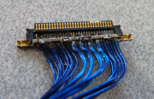
Macbook Pro 15" Retina LCD cable, slightly disassembled.

Macbook Pro 15″ Retina LCD cable, slightly disassembled.

There are now five unaccounted-for pins in the connector.  One is pin 2, in the middle of the LED anodes and cathodes; we can assume that this pin is no-connect as no wire appears to be populated in the cable.  The remaining four (pins 9, 10, 11, and 12) must map to three remaining required pins: AUX+, AUX-, and Hot Plug Detect.  It is unknown what the fourth pin is for, but it is wired in the connector.  It will be difficult or impossible to figure out which is which with simple probing.  It will similarly be difficult or impossible to determine the order of the DisplayPort lanes.  At this point there is no additional investigation that can be done prior to applying power to the panel.

Next steps

The I-PEX cable assembly is built through the hinge of the MacBook.  As such they are very expensive to buy individually, so I don’t want to damage or cut the cable, and even if I did, soldering the very, very small 40AWG wires would be a nightmare.  I am therefore designing a very simple board that breaks out the connector to pin headers.  On the same board I will also place a mini DisplayPort connector connected to pin headers, so I can use jumper wires to test different pin configurations very quickly and easily to determine the complete and correct pinout.  I do not plan to offer the documents for this PCB because it will only be useful for one test, and after I figure out the pinout I will be spinning a proper board with properly-routed matched-impedance connections.  So stay tuned for that.
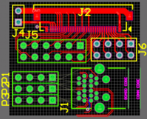
Macbook LCD test board, design in progress.

Macbook LCD test board, design in progress.

More on this when more is discovered.

Next post in this series >>
Hacking the iPad 3 LCD, A Simpler Approach Part 2: Mistakes and Fixes

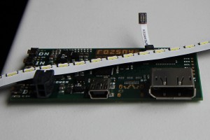
As I alluded to in previous comments and update posts, I have received and built up the boards for the simple breakout.  I used a sharpened toothpick to apply solder paste to the board, and reflowed the board in my toaster oven.  I have noted a couple of issues with the first revision of the boards:

  • The backlight power pads are through-hole.  Care must be taken to keep the backlight leads flush with the board or they interfere with the panel FFC.
  • The connector for the panel has contacts on both top and bottom.  This makes it possible to electrically connect the panel backwards.  The DisplayPort connector is on the other side of the board, which makes it reasonable to expect the panel to be plugged in backward.
  • With the DP connector on the back, it makes the board awkwardly arranged – it can’t be affixed flat to the back of the panel.  It was designed to be free-hanging on the cable since it is meant as an interface for those using the panel in a projector, but it would be nice to have an alternate mounting method for those who want to use the panel as is.
  • FInally, and most seriously, I accidentally used the source-side pinout for the DisplayPort connector.  In the source connector, from pin 1 the lanes are numbered 0, 1, 2, 3; in the sink connector they are mirrored.  This results in Link Failure errors on the host system.  This was an important lesson, and one which I’m actually glad to have discovered after only $50 worth of boards, instead of at work where I am also working with a DisplayPort design but where the cost would be closer to $3000.

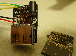
The first three issues were workable, but the last one meant the board was inoperable.  But with an Xacto knife and some 36AWG magnet wire, I was able to make the required changes.  The finished board looks like this:

Front view.  Note the magnet wire modifications in the center.

Front view. Note the magnet wire modifications in the center.

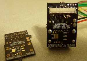
Rear of board.  Ignore the flux mess.

Rear of board. Ignore the flux mess.

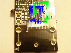
If you happened to order the Rev A boards, you too can make the changes.  You will need to cut the DP traces at the rear of the connector, and again at each of the vias where they are transported to the bottom side.  You could conceivably leave one or the other of them connected, but it is improper to leave such a long stub on a high-speed data line as it distorts the signal and causes reflections.  Then connect the vias back to the connector in reverse order.  The modifications are as follows:

Cut at the red marks, install wires across the green and blue lines.

Cut at the red marks, install wires across the green and blue lines.

I would suggest soldering the wires to the back of the DP first, then threading the wires through the vias and soldering them in place.  I think this will produce a more robust and neater end product.  I soldered the wires in the vias first, and finishing the other end was a tremendous pain.

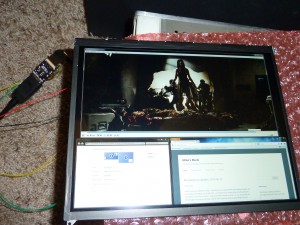
After making these changes, the board works great!  I am very pleased with the project so far.  The panel looks great – plenty of brightness, and super high resolution.  Regarding brightness, I installed 100-ohm resistors and ran the panel at about 19.5V.

First panel test.  At top is a 1080P HD movie at full scale.

First panel test. At top is a 1080P HD movie at full scale.  Plenty of screen real-estate!

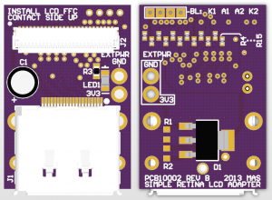
I have made the necessary changes to the board.  As it works out, when the pinout is corrected it makes more sense to have the FFC and the DP connector on the same side of the board.  This has the side effect of making the connection orientation more obvious, and allowing the board to be rear-mounted to the panel.  I have also increased the size of the backlight pads, so the wires can be more easily surface-soldered and not stick through and interfere with the FFC.

I also had the opportunity to correct the trace size for the proper dielectric constant of the laminate.  The OSH Park stackup is as follows:

  • 1 oz copper (1.4 mil)
  • 6.7 mil prepreg
  • 0.5 oz copper (0.7 mil)
  • 47 mil core
  • 0.5 oz copper (0.7 mil)
  • 6.7 mil prepreg
  • 1 oz copper (1.4 mil)

For 1 oz copper with a 6.7 mil height over plane, using dielectric constant of 3.66 for FR408, and assuming minimum 6-mil spacing, to maintain 100 ohm differential impedance, Saturn PCB Toolkit calculates necessary trace width of 8.1 mils.  I used the Saturn built-in value for FR408 when I originally designed the board, which is a little different and called for slightly smaller traces.  Using the new trace sizing and the new board layout, I was easily able to make the traces all very near to equal length (506 +/- 2 mils).  This is closer than they usually come out without a large amount of effort – in this case the board modifications only took an hour or two.

Simple interface adapter, Rev B.

Simple interface adapter, Rev B.

The new boards are on order and should be in house in two weeks or so.  I’m pretty confident now that I’ve tested the hand-wired version, but I was also confident when I originally released this board so it’s at your own risk if you want to order these boards yourself.  Here are the board documents (now with pad masters, in case you want to order stencils):

<< Previous post in this seriesNext post in this series >>

Miscellaneous updates, 2013-06-13

A short and sweet update for today.  I have built up one each of both iPad interface boards, and am having DP link failure issues with both.  I am beginning to suspect that something may be wrong with my connector pinouts.  I have pulled the documents until I can iron everything out.  My apologies if anyone has already ordered these boards and they end up being incorrect.

I’ll post an update as soon as I figure out what’s going on.

[Edit]  Damn it all.  I numbered the DisplayPort connector pins in the manner of the source-side connector instead of the sink-side.  On the sink side the ordering of the lanes is reversed (3,2,1,0 instead of 0,1,2,3).  So all the DP lane pins are wrong on both of my boards.  Super apologies to anyone who ordered these boards, and I’ll have them fixed in a short time.

[Second edit] I’ve also got a plan for how to salvage these boards if you were unfortunate enough to have ordered them.  More on that later.