Displayport adapter dongles are ubiquitous, now that DisplayPort is becoming more and more prevalent in desktop video cards. I probably have at least a half-dozen of them, connected to machines or stuck in junk drawers. You plug them in, and they work. Simple.
You are probably aware that there are two different adapter families, passive and active. The former is cheaper but is limited in the number of adapter that can be used on a single GPU; the latter is more expensive but has no such limitation. So there must be something different going on inside. But does “passive” mean here what it means in traditional electronics, that the conversion requires no transistors or ICs or other “active” components? (For a formal definition of passive vs active, see this Wikipedia article)
Before we answer that question, let’s back up a bit. Backward compatibility is an important factor in the success or failure of many new technologies. In the case of DisplayPort, if it was meant to displace DVI and HDMI on the desktop platform as its creators intended, it would need to support legacy equipment. The problem was that DisplayPort is a very different platform than DVI. Whereas moving from DVI to HDMI is fairly painless since both schemes use the same signaling standard, DisplayPort more closely resembles PCI Express than DVI. So “something” has to go in the middle, to convert from one standard to the other. And in the most basic form, this is what an active adapter does – it takes in native DisplayPort signals, decodes them, and converts them to DVI/etc. But that signal processing is complex, and adds cost to the system, which impedes adoption for some markets. For more cost-conscious applications, an alternate scheme was created – Dual-Mode DisplayPort.
In Dual-Mode DisplayPort, or DP++, the DisplayPort source (typically, a GPU) can be requested to output raw TMDS data, instead of normal DisplayPort data packets. The data that comes out of the GPU looks electrically like DisplayPort, but the data is in DVI format. A DVI monitor can’t directly use the electrical signaling format of DisplayPort, so a low-cost level shifter is required in the middle. You may now realize that we’ve answered our original question – in fact, a passive DisplayPort to DVI adapter does require active circuitry. In this case, Passive refers to the fact that the video data is not mangled in any way, whereas active adapters decode and then re-transmit the video stream. DP++ enables very low-cost adapters because the logic is simple, with all the heavy lifting being integrated (cheaply) into the GPU.
So enough talk. Now that we know what’s going on, let’s take a look at a passive DisplayPort adapter:
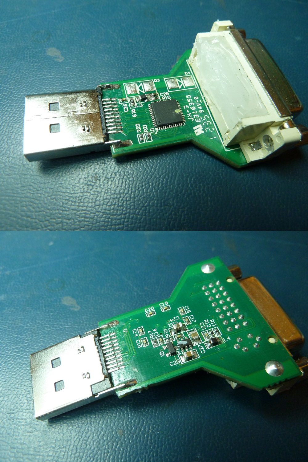
A passive DisplayPort to DVI adapter, with its casing and potting removed. I’ve removed and re-installed some components for testing prior to taking this photo.
As you can see, there is one large IC on top, which predictably handles most of the functionality of the adapter – this is the previously-mentioned DisplayPort-to-TMDS level shifter. These parts are available from a number of manufacturers – there are options from TI, Maxim, NXP, and many others. This unit happens to use a Pericom PI3VDP411LS. The competition and the high volumes of these parts have had a favorable effect on the price; the ‘411 can be had from several distributors for less than $1.50 in qty 1.
The rest of the components are primarily support components for the main level shifter IC. There is a 10A45 charge pump to generate 5V for the attached monitor (per DVI spec) from the 3.3V available from the DisplayPort, and there is a 2N3904 transistor to switch the level shifter on when a signal is received on the HPD pin. The rest are passives, mostly resistors and capacitors and one or two ferrite beads or little inductors for noise suppression. I’ve transcribed the design into a schematic, which you can download here:
It’s missing a few values, mainly because I was too lazy to pull all the components off the board to measure them and I couldn’t satisfactorily do it in-circuit. Most of the unmarked capacitors are going to be 0.1uF or 0.01uF decoupling capacitors for the level shifter.
I don’t have an active converter to tear down as well to show the differences. What I can say is that the internals will look similar, but they will operate very differently. As noted above, the complexity involved in decoding and re-transmitting the signals in an active adapter is very different than the simple level shift operation of the passive adapter. Regardless, it will probably be implemented as a single IC, albeit possibly a larger one with more support components.
I suppose that’s enough rambling on this topic. Hopefully this all makes sense!