A while back, I wrote an article on the camera in the Apple Macbook Pro A1398 lid assembly. In that article, I published the pinout of the FaceTime camera in the lid, and demonstrated how it could be wired directly to USB and function as a generic USB webcam – but not a very cheap one, since the panel assemblies are still pretty expensive.
Well, it turns out that you can buy the bare camera module for a very reasonable $5 at everybody’s favorite auction site. A visitor to this site wanted to use these cameras in a standalone application and offered to send me one to play with, in return for a little bit of investigative work. Sounds like fun, let’s take a look.
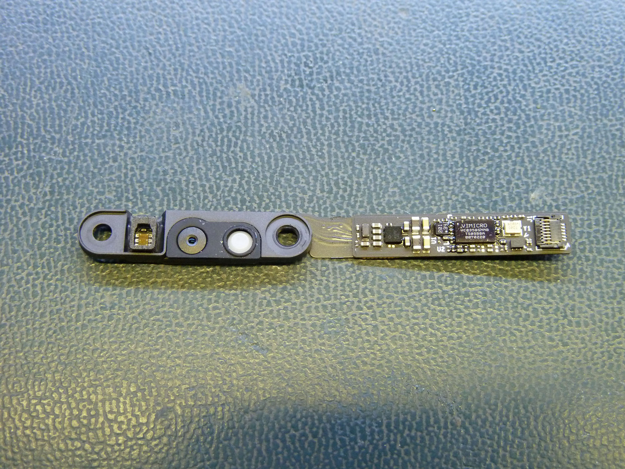
Macbook A1398 camera module, first front…
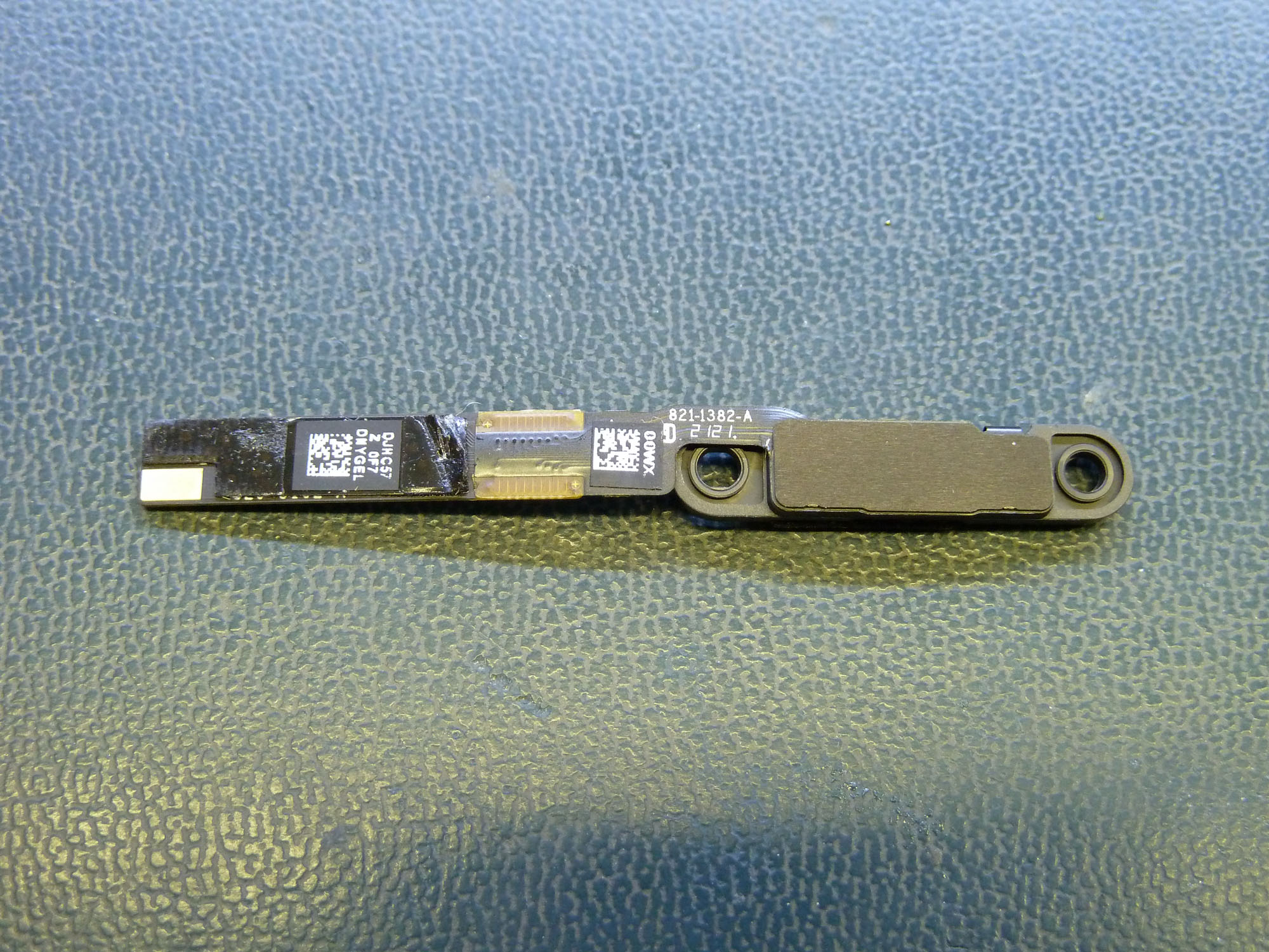
…then back.
As a recap from last time, note that this module contains not only the camera but also the laptop’s ambient light sensor (seen at left on the front view). There is a little foam ring around the ALS to prevent errant readings caused by the LCD backlight or the camera activity light. Next to the right is the camera lens, and the white circle is the activity light. The camera sensor and the ALS are on a little flex PCB which is soldered to the rigid board containing the rest of the circuitry. Many of Apple’s other assemblies are made as a single rigid-flex assembly, but the two cameras I’ve investigated have both had separate control and sensor sub-boards. I wonder if the camera assemblies would otherwise be damaged in reflow.
The top of the control board houses a VIMICRO VC0358SMMB. We can assume that this is similar to the VIMICRO VC0358PQNB, for which there is a public data brief (PDF), but this part is in a wafer-level BGA package instead of LQFP. The suggested SPI memory is probably present as the 6-pin device to the lower right, and presumably contains the USB descriptors identifying this part as a FaceTime camera. The other WLCSP to the left looks suspiciously like some sort of voltage regulator, though I didn’t bother to measure the nearby capacitor voltages to verify that. Note that although the VC0358 has microphone input capability, this board does not appear to contain a microphone.
The input connector is on the righthand side of the board as seen in the front view. The connector is a 6-pin, 0.4mm-pitch FFC receiver. I probed around the board and determined the pinout of the connector to be the same as it is on the motherboard side of the harness (pin 1 is marked with an arrow):
| Pin | Name | Description |
|---|---|---|
| 1 | GND | USB/ALS Ground |
| 2 | D+ | USB Data Positive |
| 3 | D- | USB Data Negative |
| 4 | +5V | USB/ALS Voltage In (+5V) |
| 5 | ALS_SCL | Ambient Light Sensor I2C Clock |
| 6 | ALS_SDA | Ambient Light Sensor I2C Data |
This is all well and good, but soldering to the 0.4mm connector is an absolute nightmare. It’s not something the average person is going to want to attempt. We could buy a little FFC jumper to plug in, but if we only paid $5 for the camera, having to buy more parts would negate that cheapness. Thankfully, if we remove the sticker from the rear of the module, the manufacturer has left us plenty of testpoints. I mapped the ones that connect to the connector pins, and came up with the following pinout:
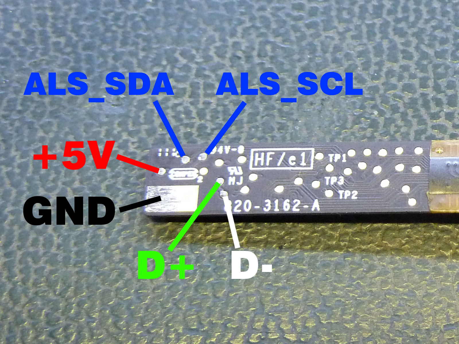
Testpoints on the rear of the camera module.
Using this scheme, I soldered on an old cut-off USB cable:

Camera wired as per the testpoint map above. The ALS pins have not been connected.
And what do you know, as soon as it was plugged in the camera was recognized the same way it was in the previous post – as a USB Composite device containing two FaceTime HD Camera devices. Again, as last time, one of the two devices has no available driver, but the camera works just fine with only one of its sub-devices installed:
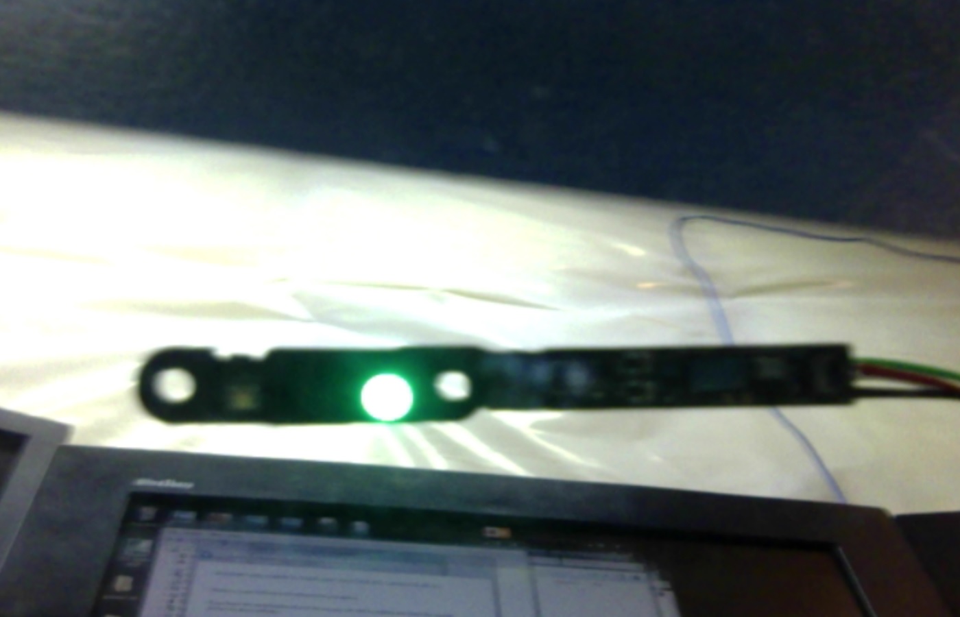
The camera takes a selfie. It’s a bit blurry, possibly because it can’t properly focus at this range. I didn’t notice that when I was taking the photo, oops.
So there you go. If you need a cheap and small USB camera for something, these are pretty easy to hack onto. Hopefully this is useful to somebody!
Thank you so much. You are awesome 🙂
I’ve got a couple of these camera boards to experiment with, I appreciate your writing up these details so that I could hack around with them. When I solder up the device, and attach it to a Windows machine, I am getting a “Device Descriptors Failed” and error Code 43. When I connect it to a MBPr, I can’t see anything showing up in the USB list (System Information or command line).
I tried swapping D+/D-. No change. USB power looks good.
Any recommendations?
Hmm. Good question. I’d like to suggest something, but both of my cameras appeared automatically (under a fully updated Windows 7 Professional SP1) with no driver issues or other errors.
Did you use the testpoints I identified, or some other method? You may want to double-check that what I posted is correct. There’s a little 4-pin common-mode choke behind the input connector (below the text “Y1”) which filters the USB data lines, you could check that your USB cable D+/D- pins actually connect to the leads of this choke, which would tell you that your soldering is good and the correct testpoints were used. Otherwise, I dunno… faulty camera?
kindly give the website address
i want to buy geniune product
Hi. Can the usb and camera wires be spliced and soldered together?
I already jacketed 4 of the 6 camera cables needed and each have this structure: on the outside it’s a black insulator, then goes a thin copper foil, then very thin sliver colored (aluminum?) wires, then another insulated cable inside so thin I had to burn the insulator to dejacket it (maybe there is better way to to dejacket very thin wires that I don’t know of, as I’m not an electrician). Inside this thin cable it looks like it’s the same aluminum wires as on the outside. What should I do with this cable?
The USB cable is shielded with 4 standard red black green white copper cables and these loose copper wires that has free contact with shield, can you tell me the function of these wires and what should I do with them?
So can you give me advice in soldering these cables?
PS English is not my mother tongue, sorry for the mistakes.
You should be able to solder the wires from a Macbook lid assembly directly to a USB cable, yes. The problem will be determining what wire is what, since all of the wires look identical. Did you cut the end off the cable, or did it come that way? Do you have access to the camera module itself, or is it still embedded in a lid assembly? (Don’t try to take it out, you’ll break the LCD glass!)
Depending on your answers to the above questions, we should be able to get pretty close to the correct pinout using one of a number of different methods. You may still need to guess the order of the data lines though; fortunately if you get them backward it shouldn’t hurt the camera.
As for how to best strip off the insulation, I’d have to do a little bit of research and experimentation. In my case, I first bought a lid assembly with an intact camera connector and found a mating connector for it, and then bought a bare camera module that I could solder straight to – I didn’t have to strip and solder the tiny wires.
Hey.
1) Could the rigid-flex part be folded or would it break by doing so?
2) Do you think a mic could directly be connect to it, if we could find the connections?
Folded how sharply, and how many times? The flex portion of the tail is about 0.25mm thick. I’ve seen minimum static bend radius figures in the 10-15x thickness range (2.5-3.75mm radius), and minimum dynamic bend radius figures in the 20-25x thickness range (5.0-6.25mm radius). You can fold flex circuits flat too, but there’s a risk of breaking traces if they aren’t designed to be flexed (in this case they aren’t). I think you’d have the best success by folding the camera module in half around a nice thick piece of double-sided foam tape to maintain the minimum radius.
As for attaching a mic, I really don’t know. The base LQFP VC0358 package has inputs for stereo digital microphones connected over I2S. Theoretically if the CSP version used on this board shares the same set of pins, they may be present on the bottom of the part. But which balls they’re be brought out on, and whether those balls are connected to convenient testpoints, is unknown – and even if we did know, we may have to rewrite the configuration data on the onboard EEPROM to enable them. It might be an awful lot of work, and it’s not something I’m immediately interested in trying to figure out 🙂
no worry 🙂 just wanted to see what possible.
what are the dimensions of the module? (by curiosity)
Argh! I keep forgetting to measure it. I swear I’ll get around to it one of these days!
no worry, decided to buy a few weeks ago and got it last week.
The measurement are not needed anymore, i just needed them so i could maybe design a small enclosure for it. ;D
Hey Mike!
My late 2011 MBP screen recently got crushed and I decided to make a project out of the Facetime HD camera within it. I believe the FaceTime HD camera and board are similar (maybe slightly different?) to the MacBook Air iSight you have been messing with.
I was able to remove the camera and the USB cable within the upper enclosure. My plan is to leave one end of the USB intact (for the camera board), and to splice the other end to a USB cable that I can plug in to a Mac Desktop. Ultimately, I plan on removing the guts of an old iSight webcam (available 2003-2006) and placing the FacetimeHD camera/board within its shell.
Anyways, I am having trouble identifying which wires to splice where… I understand the GND/D+/D-/5V of the USB I am planning to splice to (4-wire without the i2c wires), however I cannot figure out how to assign these to the cable I pulled out of my old laptop (6-wire with i2c), because these are not color-coded in the standardized fashion. Below I have a link to an image that illustrates the 6 wires of the MBP camera USB (4 green, 1 red-ish, 1 copper-ish).
http://imgur.com/a/eiKzF
Any thoughts on how to test for the power/ground wires of MBP’s usb cable? Also, are there any USB cables available that I could splice to that would enable the i2c capabilities?
Thanks!
The algorithm I used to determine the pinout of the camera was:
1. Find the GND pin. This is probably connected to the shell of the connector and/or the mounting pad(s).
2. Find the +5V pin. If you have found the GND pin, first find a capacitor somewhere on the board and figure out which of the two pads is GND (one usually will be). Then move to the other side of the cap and see if there is continuity with any of the other pins in the connector. If not, repeat with the next convenient capacitor. Invariably there will be at least one capacitor between +5V and GND on the board. Start with the largest capacitors, as they are the most likely to be used for bulk +5V storage.
3. Determine USB pair versus I2C pair. The cameras I looked at used I2C for the ambient light sensor, which is on the sensor flex board. Two of the pins on the connector should show continuity to the ALS, if you can get to it. It may be simpler to probe the flex board connector, if this assembly has a detachable flex section. The cameras I looked at also both ran the USB lines through a small common mode choke directly behind the connector. It looks like your camera may also have one. Even if not, you should be able to determine which traces belong to USB because they will typically be run on the outside of the board, and will be run next to each other with consistent spacing.
4. Once you figure out which pair is USB, it’s up to dumb luck. I found that my connector matched the standard USB pin order, GND/D+/D-/+5V. I’d start there, but it’s not inconceivable that Apple could have switched things up, so if it doesn’t work that way, swap the wires – you won’t hurt anything as long as your power pins are correct.
5. Ditto for I2C. Try it one way, see if you can read the sensor, and if not swap the wires. My cameras were pinned (starting with pin 1) GND, D+, D-, +5V, I2C CLK, I2C DATA.
As for cables to read the I2C… I don’t know how to help you there. Were it me, I’d probably use a little MCU as a USB-to-I2C bridge. But mostly I don’t care about the ALS so I just leave it disconnected.
Hope this helps!