Last week I wandered across a thread over at the Overclock.net forums talking about my iPad controller boards. It would seem there is a growing demand for ultra-high-resolution multi-panel displays amongst the gaming and power user crowd. The recent releases of high-pixel-density panels in consumer devices means they have become quite accessible to the average hobbyist.
There are a couple of niches that these panels best fill. For the road warrior, the compact size of the iPad panel might be nice. For the graphic designer, the Macbook Pro Retina panel offers good performance. But for the gamer crowd, where high refresh rate is most desirable, neither of these panels quite fits the bill.
As it so happens, boutique PC manufacturer Alienware continues to push the limit (and budget) of the gamer-on-the-go. Enter the Alienware m17x, a megalaptop with an optional 17.3 inch, 120Hz, full HD 1080p, 3D-capable display. That’s an awful lot of display, and found in its native habitat the privilege of using it would start at $2000, but thankfully we can find replacement panels in the usual places for about $100.
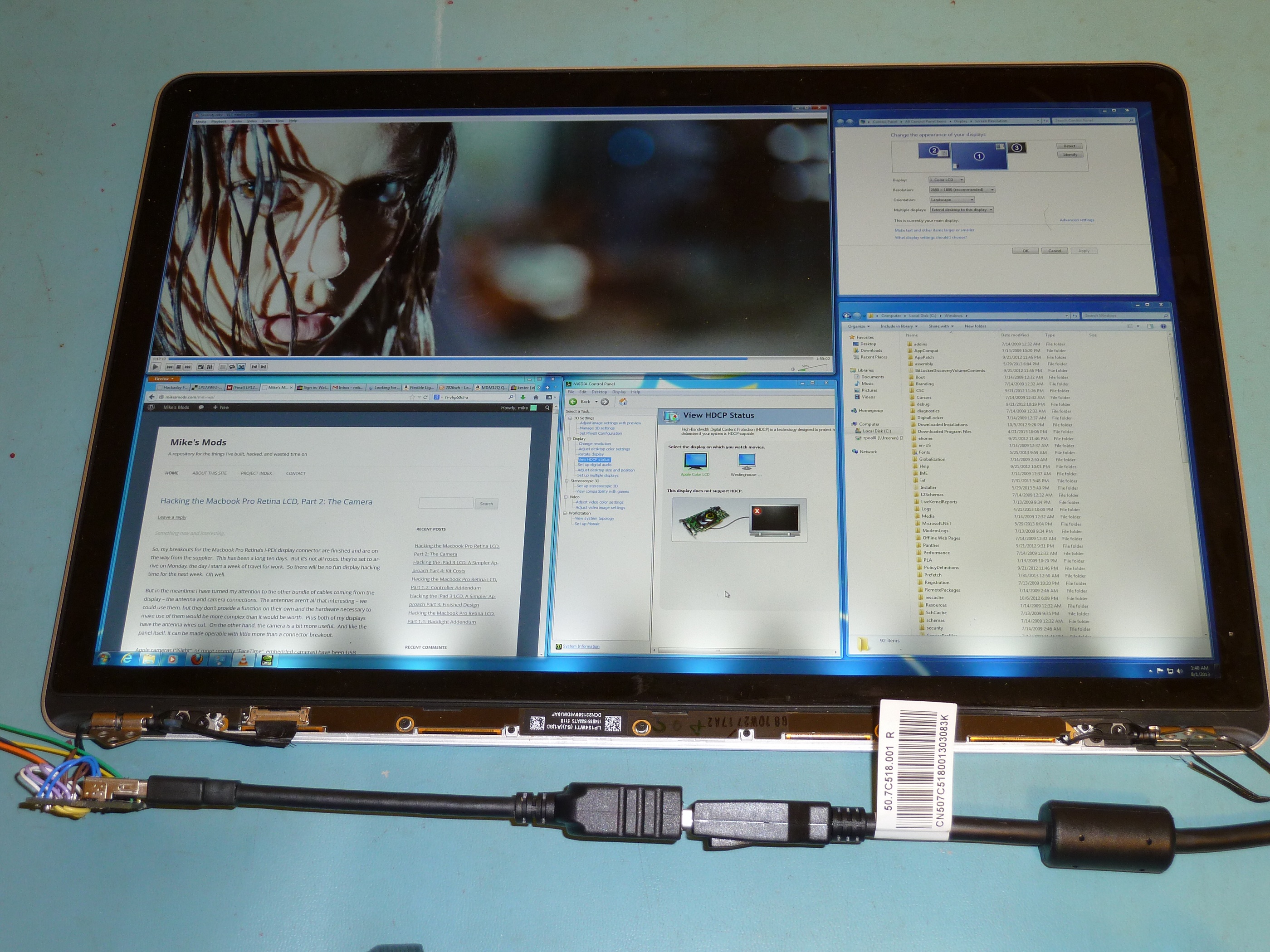
Now, 1080p doesn’t really hold a candle resolution-wise to some other panels such as the Macbook Pro Retina display at 2880×1800. But the major advancement here is the 120Hz refresh rate, which promises to offer better gaming performance and less video tearing. I don’t game much, but I was curious about the combination of features in this panel, so I bought one to play around with.
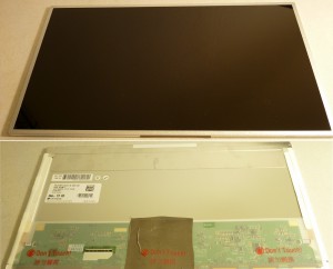
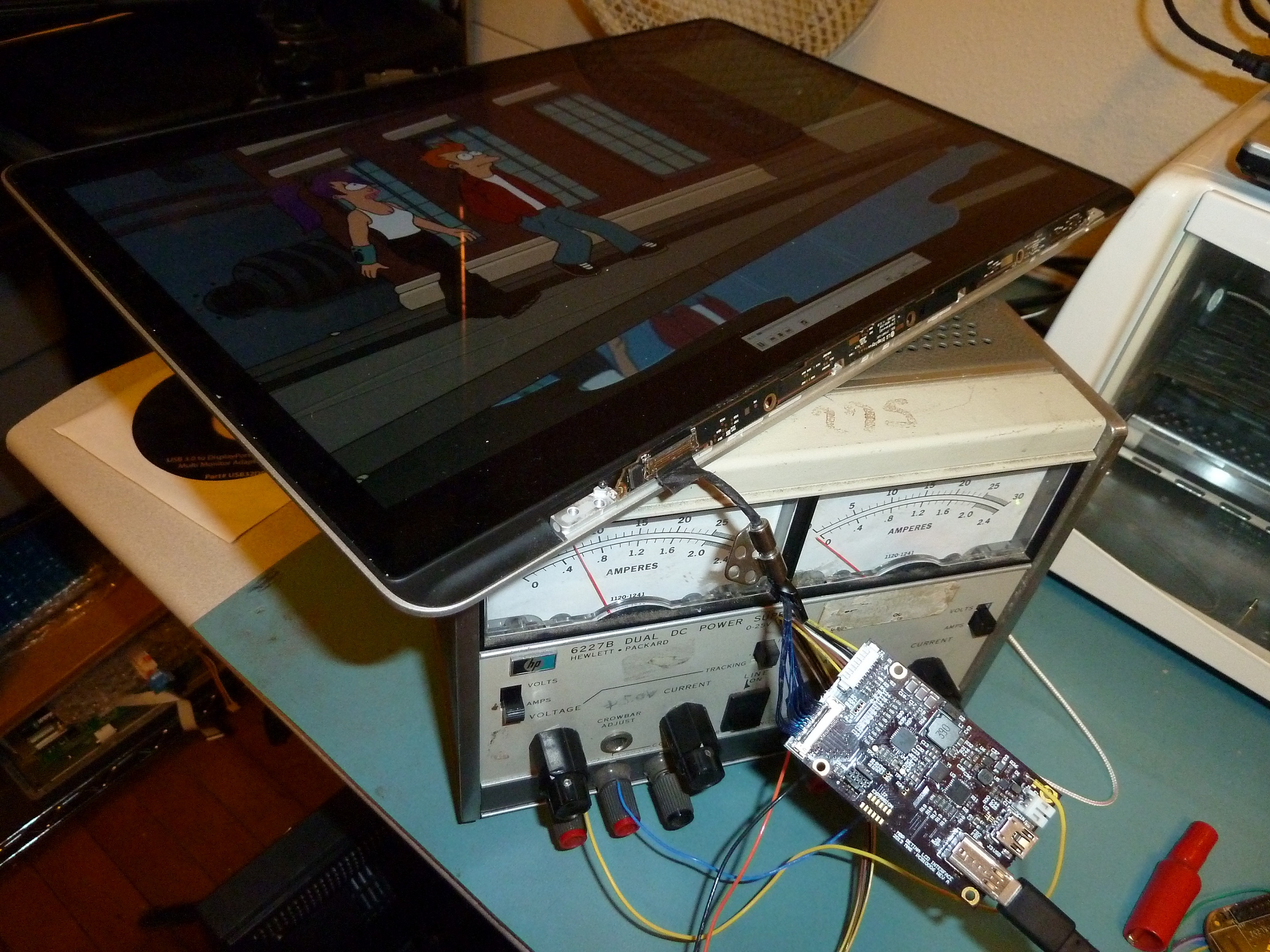
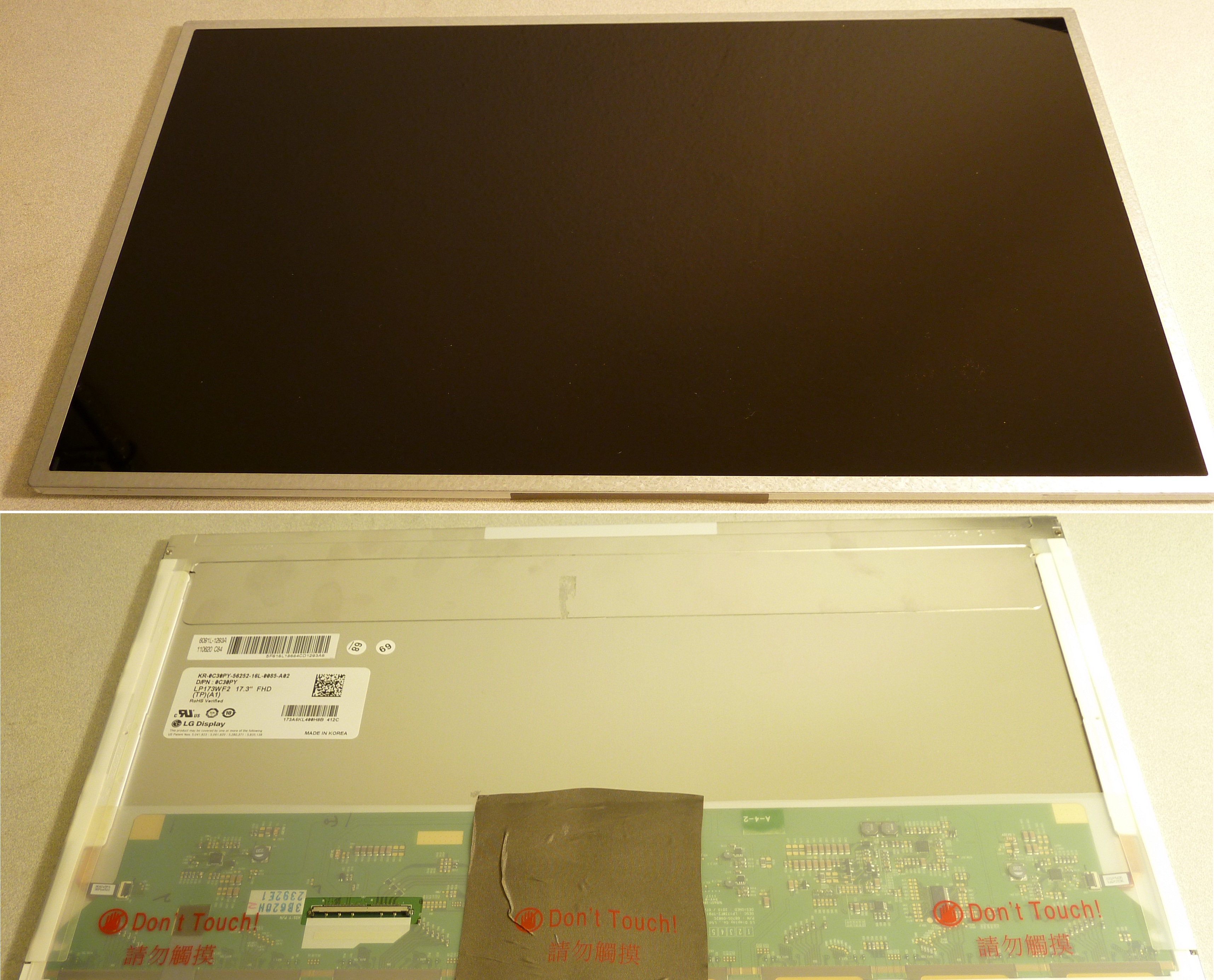
The panel in all its glory. Note that I’d already removed the square of conductive shielding cloth before this photo was taken, which is why it is wrinkled.
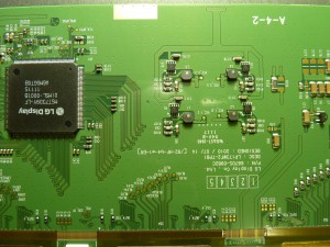
This is the LG LP173WF2(TP)(A1). We can pull all the necessary specifications from its datasheet (mirrored locally here). It is driven with 4-lane Embedded DisplayPort, just like the Apple Retina panels. However, interestingly, this panel is driven with 5 volts, instead of the typical 3.3V. Further unexpectedly, the panel electronics draw a shocking 2.3 amps (11.5 watts), which does not include the backlight. I bet the stock 86Whr battery in the m17x doesn’t last very long.
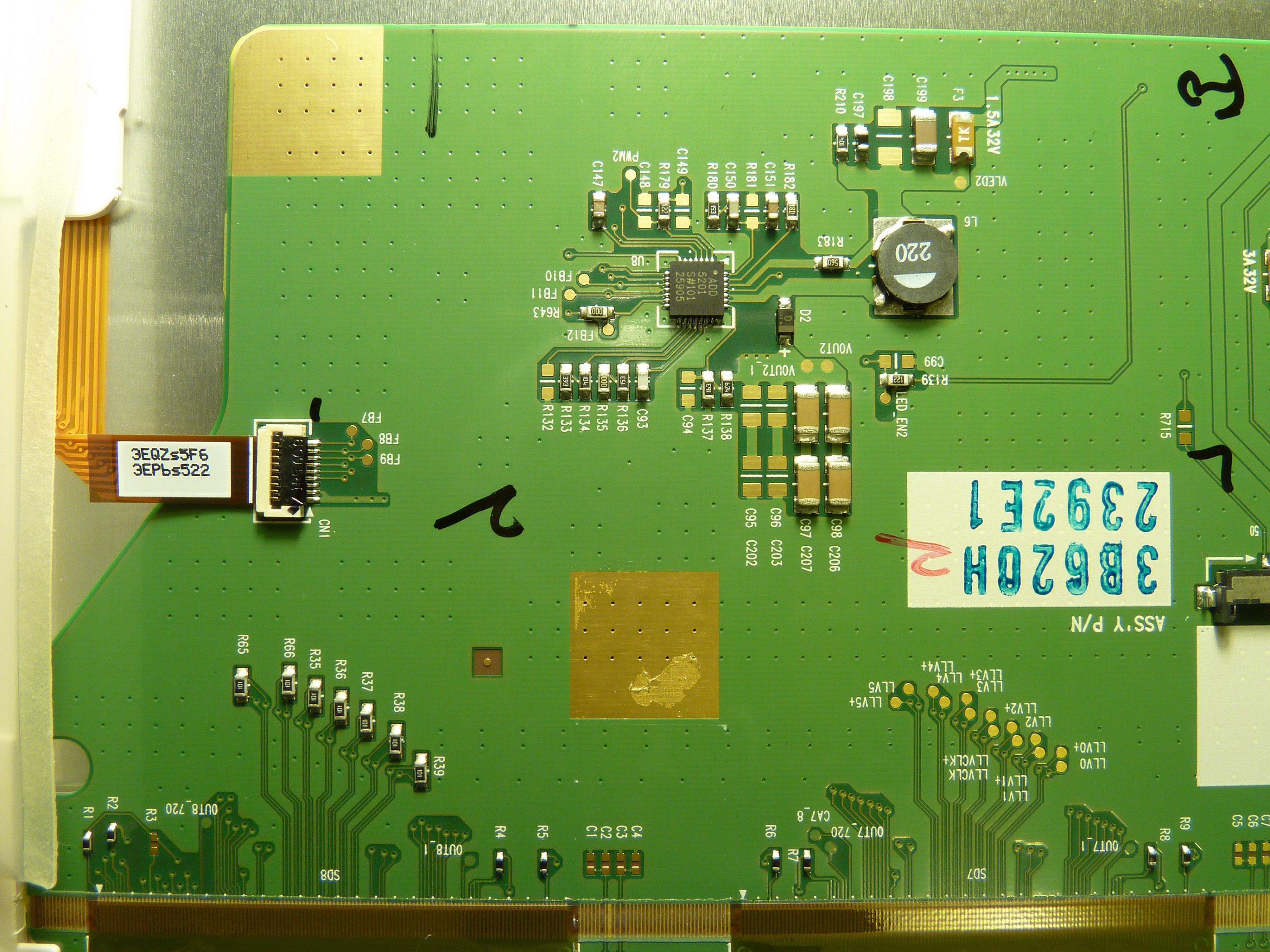
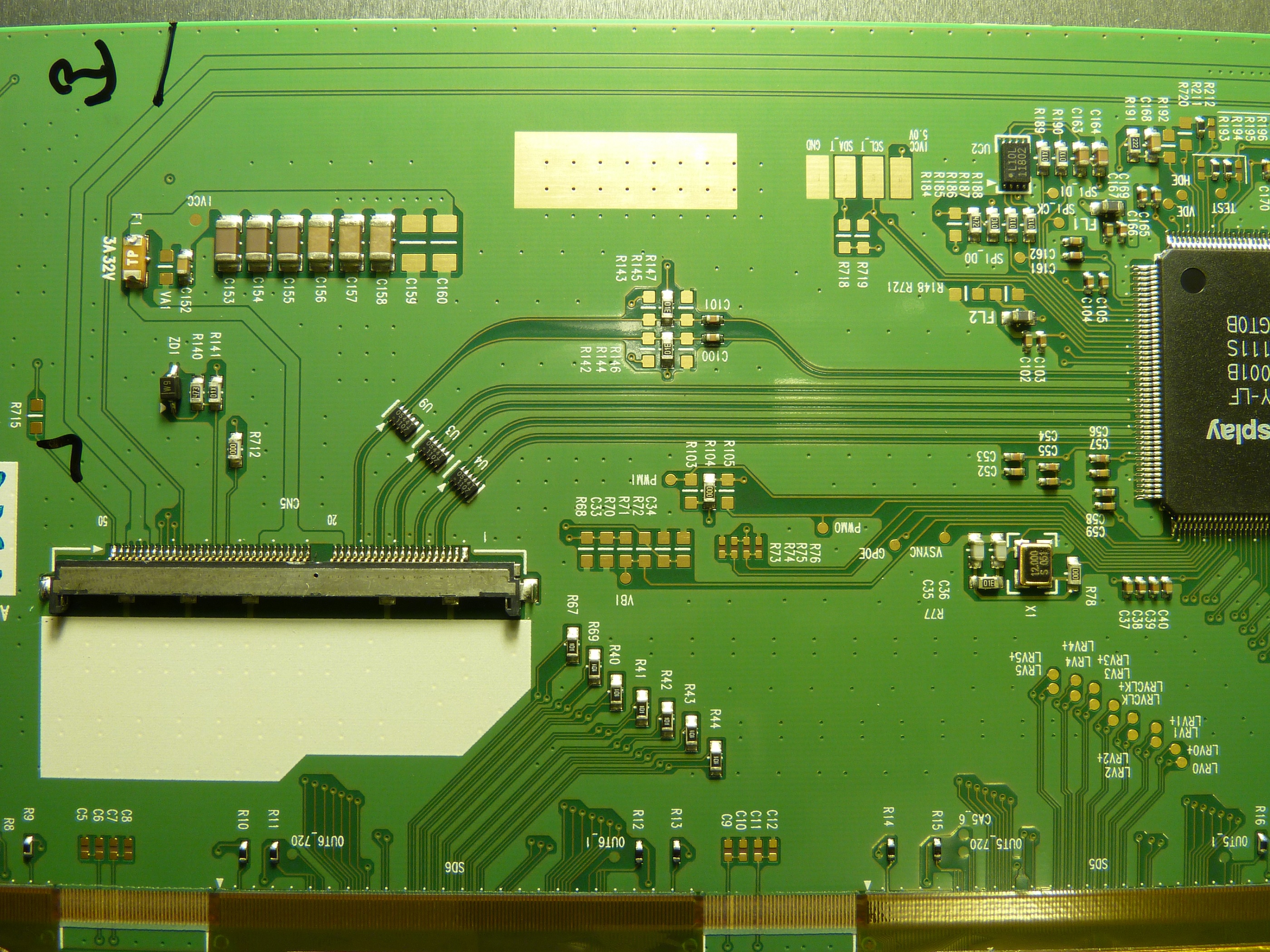
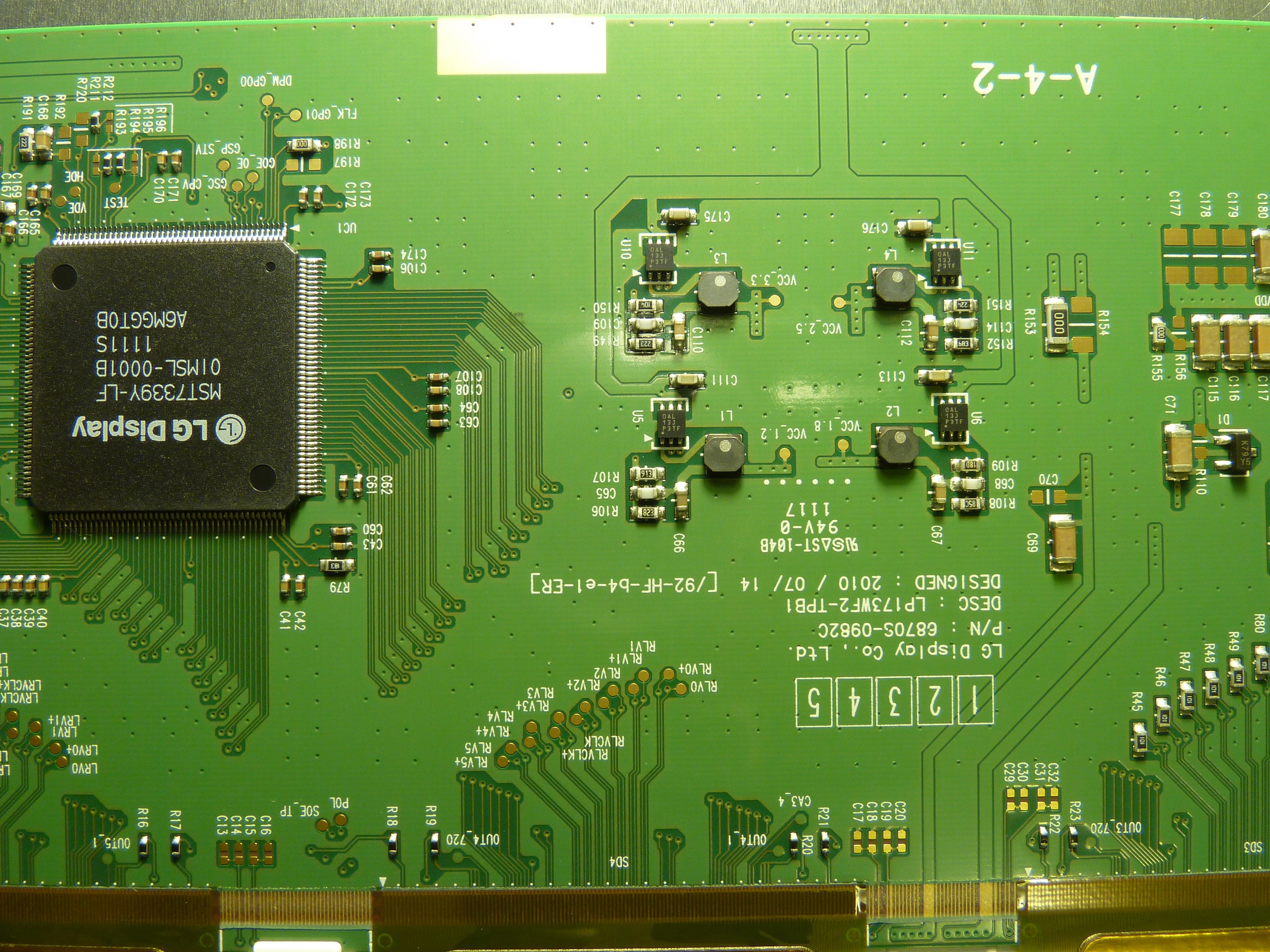
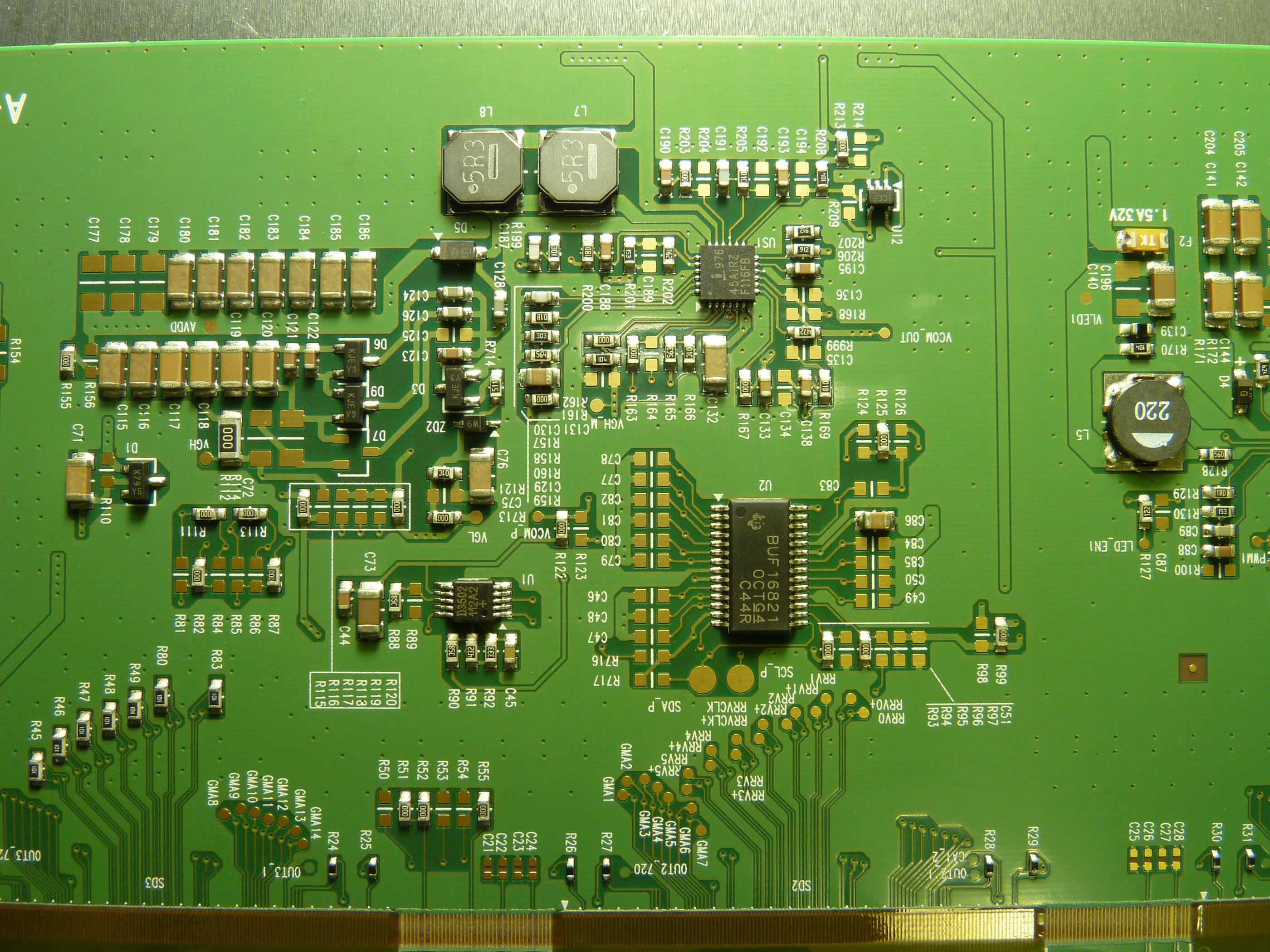
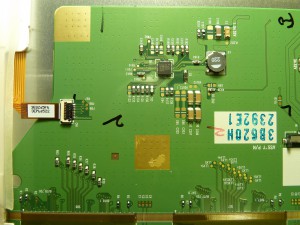
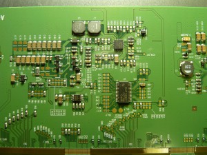
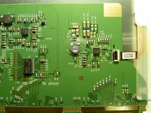
Speaking of the backlight, a notable difference between the Retina panels and this panel is that the LP173WF2 contains onboard backlight drivers, eliminating the need for external drivers. SImply apply between 7 and 20V, a logic-high Enable signal and a 5-100% duty cycle square wave, and the rest is taken care of. The backlight claims to draw another 11.6 watts. Here are some high-resolution shots of the panel’s backlight drivers and controller electronics:

Just like every new display, this panel has a different set of power and control requirements to all the others. Thus, a new controller board will be designed to fit the particular needs of this unit. But we’ll get to that in due time.
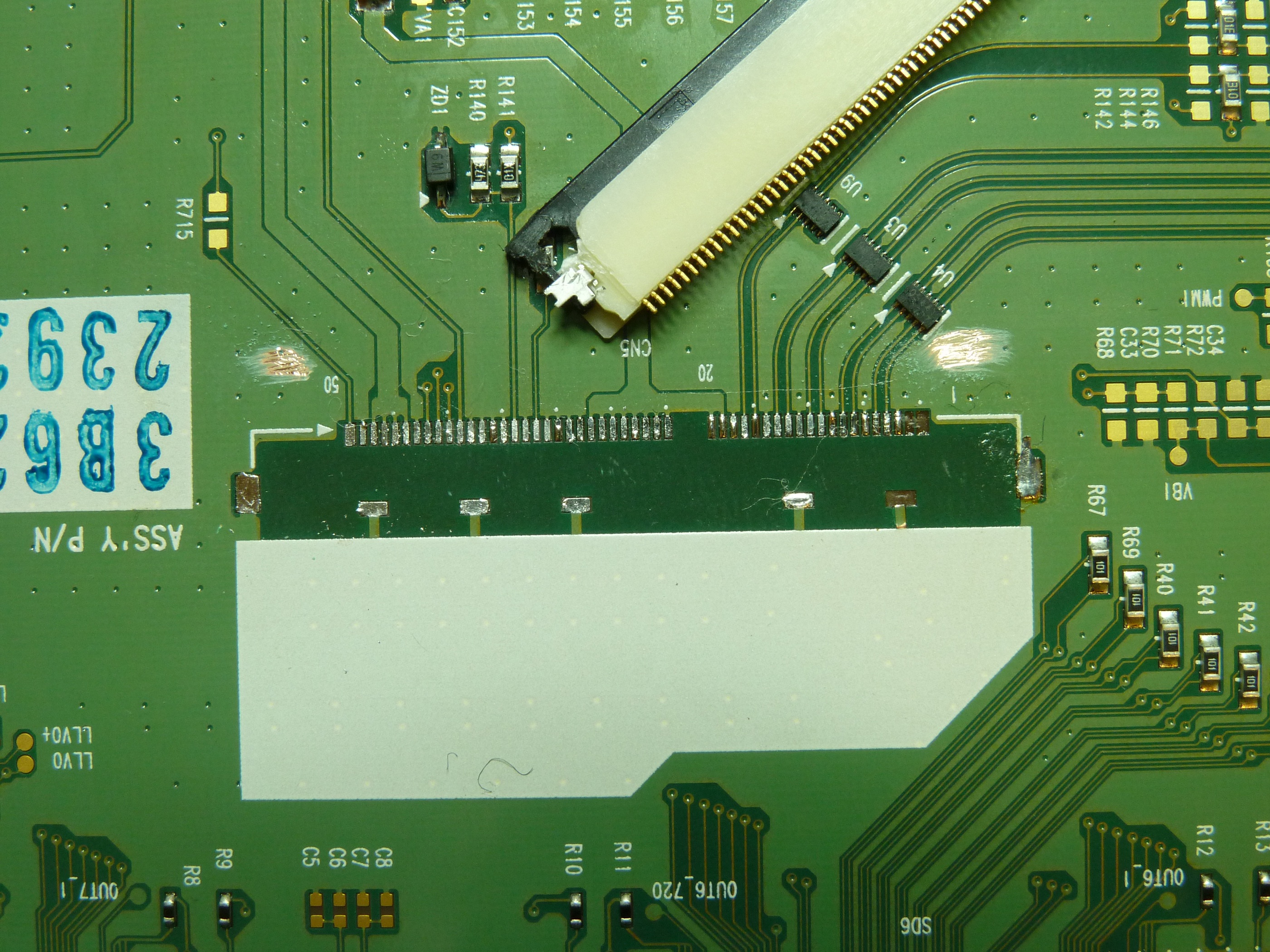
First, let’s take a closer look at what we’re working with. Seemingly similar to every other panel, this one has a unique connector and pinout. In this case it is a JAE FI-VHP series 50-pin connector, FI-VHP50S-A-HF11, mating connector FI-VHP50CL-A. This is a problem for a couple of reasons – first, this appears to be a new part which is not currently available at any of the usual distributors, second, even if we could find it, it’s probably beyond the capability of most folks to populate the 0.5mm pitch connector with the very small (32-42AWG), preferably shielded coaxial wires.
So what do we do? We could order a reel of 3000 pieces direct from JAE for some thousands of dollars, but that’s not a wise investment unless we’re likely to use a couple thousand pieces, and then we still need to assemble the harnesses (and soldering 50 tiny wires on 0.50mm pitch won’t be fun). We could draw up a specification and order custom harnesses from a supplier, but still unless the quantities are quite high they will probably be more expensive than we’d like. We could buy used assemblies from the source laptop on eBay, which we can get in single-piece quantities, but these are not very prevalent and are extremely expensive. Or we could replace the connector with a more widely-used type, which requires us to modify the panel but is comparatively very inexpensive and easy to come by. I have opted to take this last approach initially, and will reevaluate the other options if demand arises.
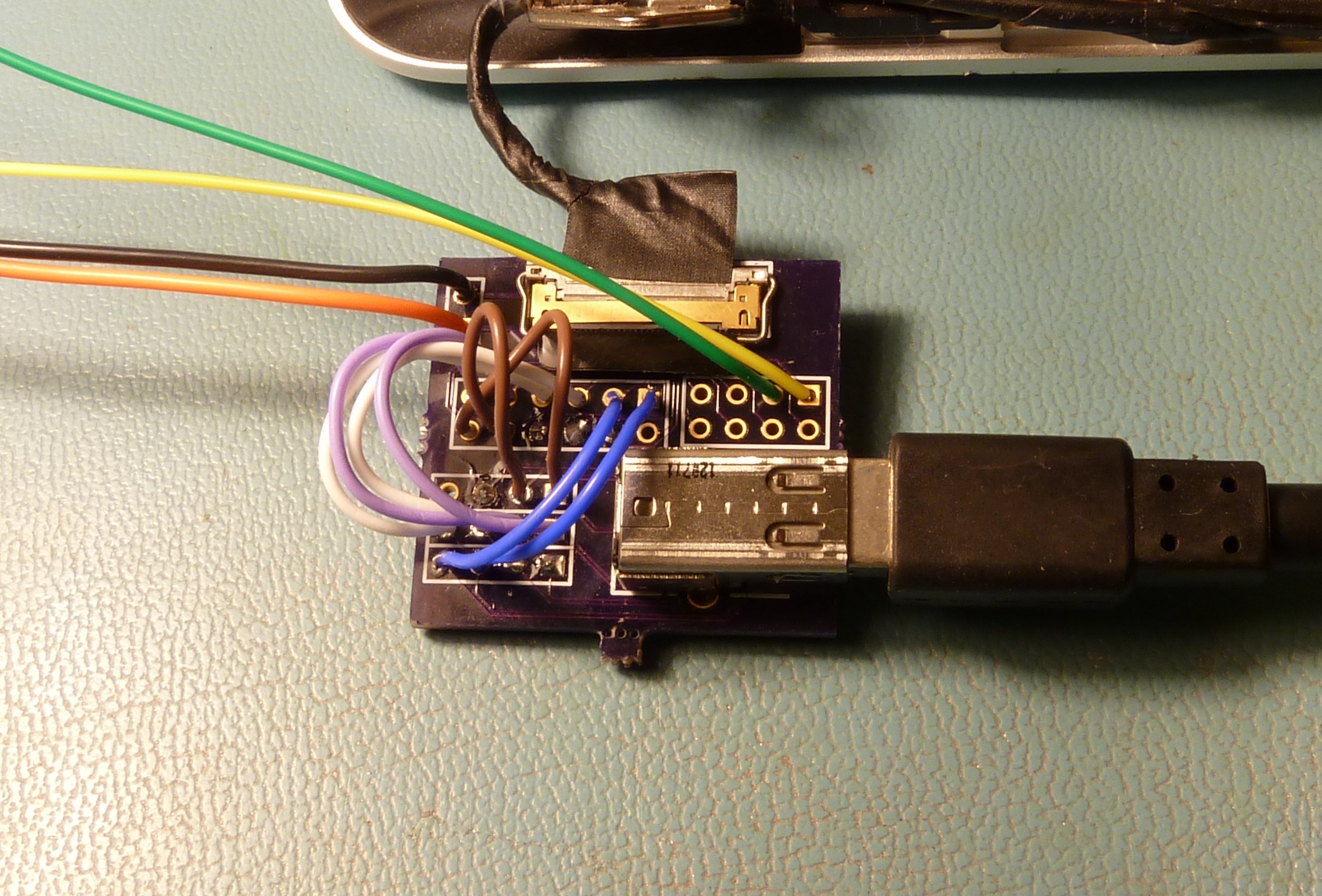
Originally I contemplated designing a flex circuit harness to solder directly to the panel and break out into an iPad-style 0.3mm contact pattern. I still think this would have been a fairly slick solution, but when I attempted to draw it up I found that this contact pattern is not possible for the low-cost prototype houses to produce – the traces are too small and the pads are too close together. So as a runner-up option I have chosen to replace the existing connector with a 0.5mm ZIF FFC socket, FCI 62684-501100ALF. By using a standard connector like this we can also use standard FFC cable assemblies, which are very inexpensive and come premade in a variety of lengths. I bought a 2-inch cable which seems about right.
Original FFC concept, using my full-feature iPad board as a stand-in for the new board.. Ultimately this plan proved too complex for the “budget” flex board suppliers, and I was unwilling to pay for a “real” board house.
The downside to this approach is that since the VHP-series connectors have a 3-pin-wide break in the middle, the 50-pin connector is actually the width of 53 pins. Luckily two of the pins on one side are No Connects, but we are still forced to choose between losing pin 1 (“2D/3D Contents Communication”) and pin 48 (DP Lane 3 shield ground). I have opted to offset the connector to carry the ground connection, and will re-wire pin 1 to one of the three unused pins in the middle of the connector if I get around to it. Actually if you look at the controller photos it appears as if pin 1 is connected through a non-populated resistor and is thus a no-connect, so I may not bother.
The removal of the existing connector took a surprising amount of effort. The FI-VHP series has stabilizing legs soldered to the board on the three sides without contacts, so all four sides are soldered down. This makes removal of the connector, particularly without harming nearby components, quite difficult. To reduce heat transfer to the heat-sensitive plastic diffuser films, I propped the controller board up off the rear surface of the panel. I would like to have flipped the controller board over and solder it against a flat surface to avoid stressing solder joints, but the board is held by a small jog in the plastic frame and I felt uneasy putting enough stress on the connecting ribbons to move it.
An embarassing amount of time later, the original connector was removed, losing only one mount pad and the two No Connect pads in the process (probably because my heat was too high):
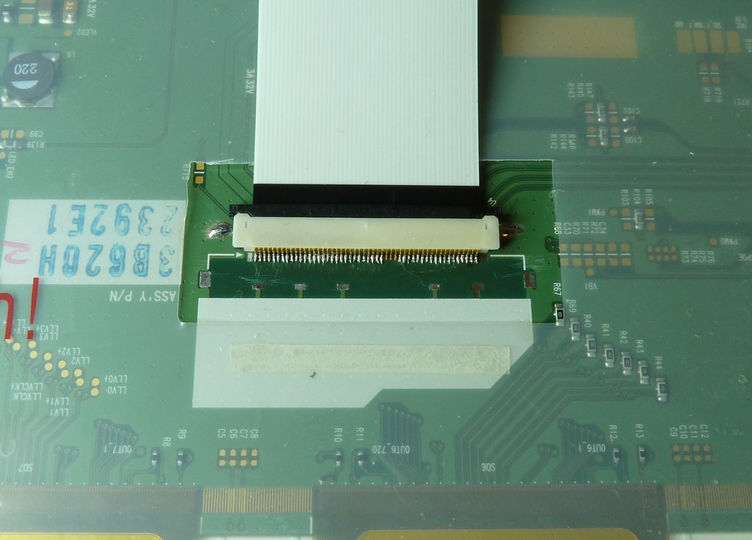
Connector removed (but pads not yet cleaned), new connector modified to clear U4, soldermask removed for side feet.
Now, to understand my next move, it is important to note my grand plan for this panel. I’ll illustrate the plan with a 3D model as soon as I have time to draw something up, but for now words will have to suffice. The panel will need to have a controller PCB attached, to generate the backlight dimming signal and break out the eDP to a more accessible connector. The various connectors required and the cables attached to them are bound to be heavy, so I don’t want to attach my board to the thin plastic protective sheet over the LCD controller. I’d much rather stick it directly to the exposed sheet steel chassis. To achieve this the ribbon cable must point up. I could either accomplish this by putting a sharp bend in the ribbon cable, or by populating the connector upside-down. The latter option has the disadvantage of interfering with one of the eDP ESD protection diode arrays, but it provides the benefit of also allowing me to solder down the outer feet to provide strain relief to the tiny solder joints. This is ultimately the path I chose.
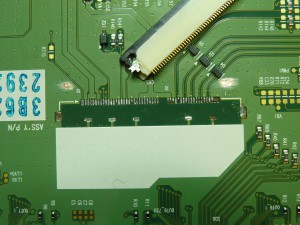
I scraped away some soldermask to make pads for the connector’s feet, and trimmed off the corner of the connector and latch to clear the protection diode. Then, time to solder the pins. I had some trouble getting the solder to flow between pin and pad – because the connector “only just” fits behind the diode, there is almost zero exposed pad behind each pin, which means there is no rear solder fillet to span the gap. Probing the pins with a dental pick after the first pass noted several wiggling pins, on which solder had flowed over and up the pin but not down around it. I went back and pressed down on each pad while applying a little more solder and that seemed to fix things. And after more time than I am comfortable admitting to, and on my third connector after ruining two, it was finally done. Here’s what it looks like now:

Looks pretty good, if you don’t look too close. Don’t let the photo size fool you, those pads are really really tiny.
Ultimately I was unable to reflow it with hot air and unable to solder it with the finest tip I had on my home soldering iron so I had to take it to work and use the professional soldering station there. I often say that the things I design are difficult to build up, but for some reason – probably due to the delicateness of this assembly – this one was the most difficult soldering job I’ve recently had to do. I sure hope a source for the correct connector appears, because this was no fun! Actually, to be fair, after I started using the pro soldering station things went a whole lot better, so maybe if you have good equipment it’s doable. But it’s certainly no cakewalk.
That’s about all I feel like doing for now. I now need to spend some time hacking the other end of the ribbon into one of my iPad or Macbook boards in order to apply power to the panel. As a happy accident, as I noted in an earlier post, I have a set of boards that I designed erroneously to break out a 0.5mm connector which I thought was used in the Macbook, so maybe I can leverage those to get up and running faster. We’ll see.