Wherein Mike is schooled by more seasoned hackers.
I don’t have enough for an additional full part to this series, but some information has been brought to my attention in regard to my findings in the last post and it’s useful enough that I have opted to write this addendum.
In the comments for the first part of this series, and in a followup email to the comments, fellow Retina display hacker Daniel Rozsnyo let me in on a clue regarding the backlight for the 15″ Macbook Retina panel. The iFixit article notes 48 LEDs are present, which is correct. But while writing the previous post I attempted to drive the backlight to test my pinout and gave it what I thought was more than sufficient voltage (up to about 35V) and… nothing. Which made no sense – if indeed there were 48 LEDs, and they were in six sets, then there should have been 8 LEDs in series at 3.2V apiece for 25.6V required. But nothing happened.
Daniel let me know via email that I was missing one essential piece of information: there are two LEDs in series in each package. So while there are 48 LEDs, there are actually 96 dice, in series sets of sixteen, not eight. Daniel sent me the following photo of the LED strip out of his panel, in which you can almost make out two dark spots in some of the devices – and at very least you can see that the white plastic cases are semi-divided in the middle.
LED strip out of the Macbook Retina panel (in this case the Samsung panel, but they seem to be very similar).
I would never have come up with that without a little prodding, so thanks Daniel. I have seen devices like these (Nichia and OSRAM make plenty of different models), but never with two series dice before. The reason for using these unique devices may have been the desire for more even lighting across the display surface. A reasonable amount of the linear space along the base of the panel is wasted in solder pads and device packaging, so stuffing two LEDs in each package halves the amount of overhead and allows the LEDs to be packed closer together, which reduces backlight banding.
With this new knowledge in hand, I soldered in some jumpers and applied about 46V to one of the strings through a 100R resistor and sure enough, it lit up. IPS displays like this one are naturally black, however, so that wasn’t very exciting. I also soldered in jumpers to apply V+ to the LCD controller (which I set at 3.0V, which should be within the range of both 2.5V and 3.3V panels – since remember I don’t know what the proper driving voltage for this panel is), and when V+ is applied, the panel slowly drifts to gray/white. I am not yet sure whether this is good or bad, but in any case it allows us to look at the backlight dispersion pattern in a bit more detail.
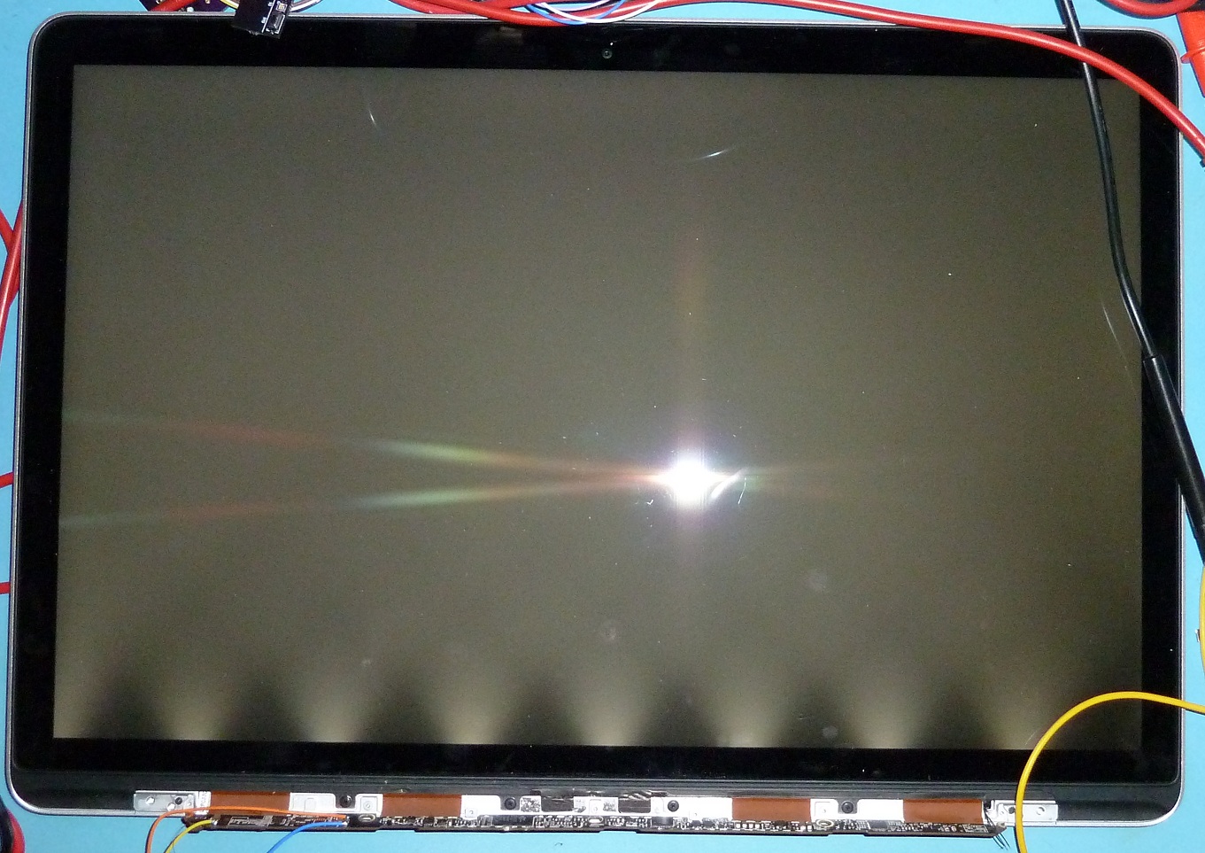
The Macbook Pro Retina LCD assembly, with the panel plus one LED array powered.
I said this at the end of the last post, but I think I mean it this time: This will probably be the last I touch the display until I get my breakout boards in, which should be late next week. I have contemplated soldering in bunches of tiny magnet wire flyouts and wiring the panel into my iPad test boards, but I don’t want to damage any more than I already have.
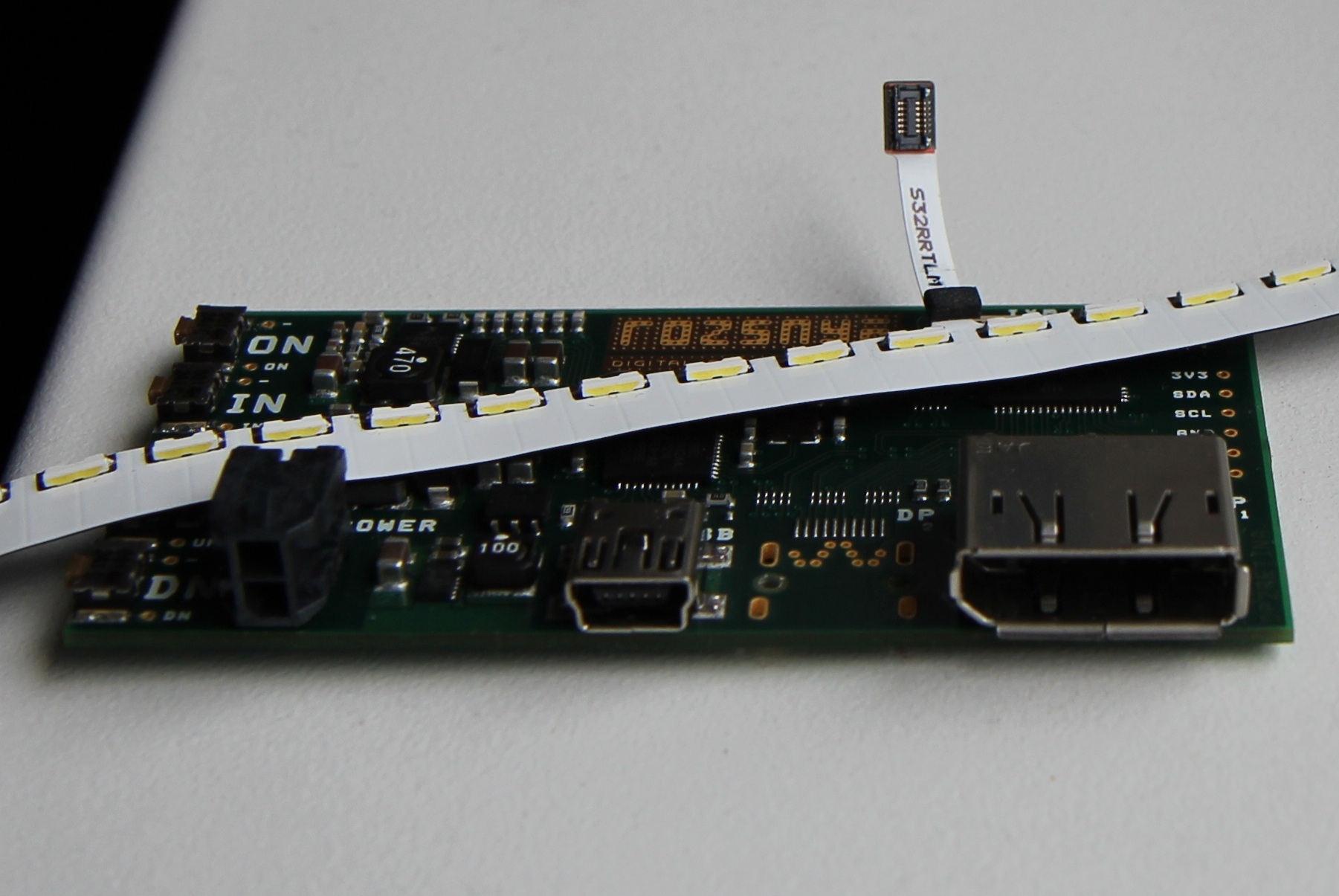
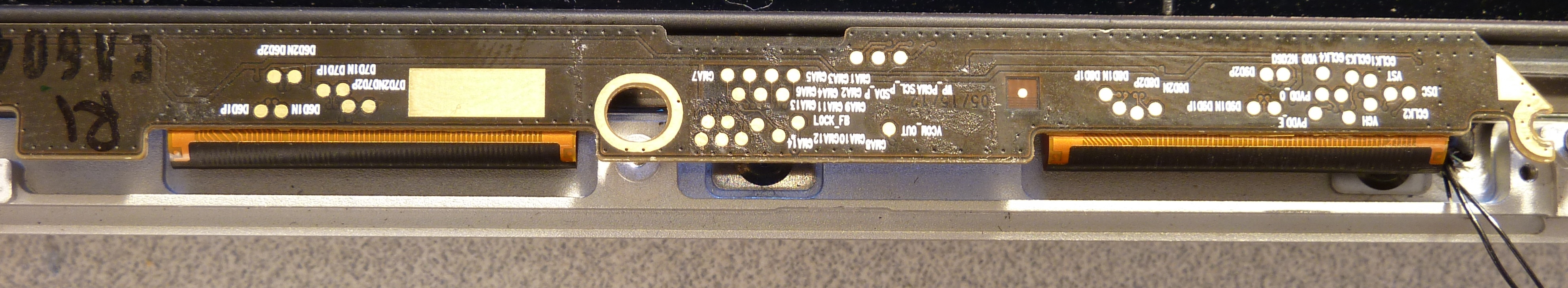
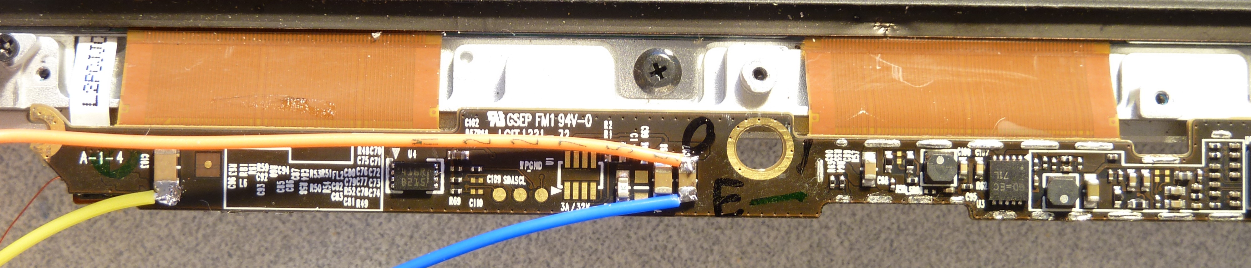
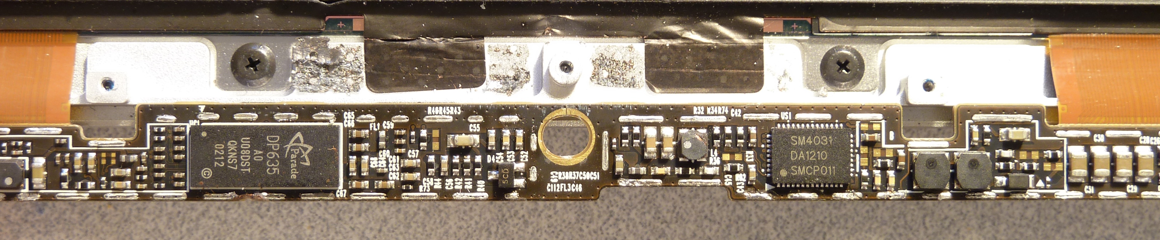
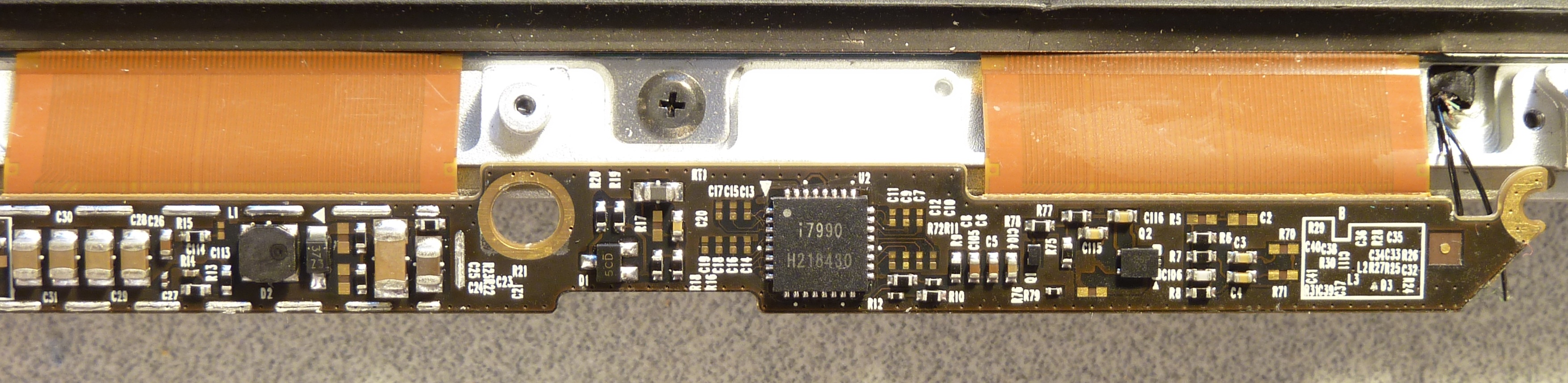
Which reminds me: I removed the EM shield frames from the controller, so now you can more easily see all the parts that may have been obscured before. I also removed all the insulator stickers from the top side, revealing a bunch of labeled testpoints. Enjoy! (Ignore the jumper wires, eh?)
<< Previous post in this series … Next post in this series >>
Mike, where are you? I already got it working! More info my website 🙂
Dammit, you beat me to it! My breakouts should ship tomorrow and be in hand by the weekend, at which point I’ll write some more. For now, working on odds and ends from the rest of the projects on my list.
Congrats on the accomplishment!
Now, following the trend… first one to build a breakout for the iPhone Retina display wins the big prize. That one’ll be much more interesting – first it is required to convert the source to MIPI DSI. To my knowledge no silicon exists to convert TO DSI (although DSI->x is plentiful).
How you plan to manage the initialization sequence? MIPI DSI is not just data and there is no standard negotiation like the one in DP using DPCD.
And I have to correct you – there is a silicon for that kind of conversion and I have already a module with it (not for iPhone) so I think it would not be fair to take the challenge 🙂
Oh… so Toshiba makes a whole line of stuff, including RGB->MIPI DSI (TC358768A). I hadn’t looked into it that hard before. Of course, I can’t get ahold of that, so it’s a moot point. Did you build up the unit yourself, or purchase it from a third party?
I was not aware of that Toshiba chip, back then they were offering only CSI bridges.
The SSD2828 has 4 data lanes, so it can drive a FullHD mobile phone LCD, which is one of my projects. The chip comes in QFN (the Toshiba is ultra fine pitch BGA). There are some evaluation modules (made in china) but I rather designed my own board – in the same way as other modules are done: RGB input on one B2B plug and MIPI output on the other B2B. That output would then attach do a display specific breakout board, which holds the multiple power supplies required by the LCD itself.
So far all the modules are very specific and different, but maybe one day I standardize the interfaces for similar function, so they would be easily exchangeable – that would lead to a great development system and others could build their own modules or application specific assemblies.
Is there a distributor that sells Solomon parts in small quantities? I’m sure I don’t have the buying power in my hobbyist activities to interest Solomon in selling to me.
Hi Mike. I’m in desperate need of some advice. I bought a 15″ Mac Pro retina (damaged by liquid).
It powered on, but the display didnt light up. I disassembled it, and found that the backlight fuse on the logic board was open. I inspected the ipex connector, and found that pins 1 and 2 was melted away. I followed the track off pin 1 to a capacitor. I cut the coax wire on the cable from pin 1, soldered it to the capacitor on the logic board. I replaced the fuse. The display lights up exactly like on your pic (only one led array). Pin 2 is allso fried and not bridged. Acording to your pinouts I see that pin 2 is not connected). Why do I only get one led array active?
Hmm, how odd. Well, the very first thing I’d do is check continuity between the I-PEX and the backlight connector to the left of it, to make sure no additional traces were damaged. If one channel works it means the common anode is working, so that’s a good start. If you’ve got a proper current-limited bench supply and a steady hand, you could also try applying a DC voltage (~45-48V) directly to the connector to determine whether the backlight strings themselves are all still alive.
It could also very well be damage to the logic board, possibly destroyed transistors near or in the backlight driver. I’m not familiar with the logic board construction, though, so that’s about all I can offer you in that area.
Thanks for your reply. Am I understanding correct that the problem might be a broken track on the pcb between led k1 and led k6?, or should I look at pins vcc (28-30)?
That thin coax wires are a mission to solder.