Welcome back! It’s been more than a month and a half since my last post on the Macbook Pro Retina panel – damn my “real job” and the time it consumes. But we’re here now, so let’s dive into things.
In the previous two posts on this subject, I have talked about two boards that I have been developing for the 15.4″ Macbook Pro Retina display assembly: a breakout for the FaceTime camera, and the main display controller / backlight driver board. Well, in the month-and-a-half that has elapsed, both boards have been received and built. Let’s start by taking a look at the former.
Camera Breakout
When I went to order these boards, I did so immediately after the cutoff for the current OSH Park 4 layer order, so the estimated delivery time was three or four weeks. Unhappy and impatient, I held off and instead ordered the board as 2-layer for more instant gratification. The two inner layers are only GND, so this is possible without too much trouble. It throws off the impedance of the USB traces probably significantly, but as the entire trace length is a half inch or so, I figured it’d be close enough for at least temporary use.
So the boards arrived a week and a half later. I immediately noticed something interesting and bothersome. Board fab houses typically require a gap between the edge of any copper and the routed board edge. If you are making a small board and including mounting pads for screws, the pads may consume a large percentage of the total board area – in fact, the pads may well drive the overall dimensions of the board, and larger dimensions mean greater board cost. I wanted this board to screw mount, but even the 2-56 screws I designed for needed quite significant pads. I decided it would be nice to trim the amount of room wasted on mount pads by clipping the pads at the board edge, allowing the screw to extend into the no-copper area at the edges of the board – it really only drops a few cents from the board in this case, but it makes me feel better.
So in Altium Designer, I made a small Pad on Multilayer (the magic layer which is copied to all other layers), then made a Polygon in the shape of a circle with a flat edge and also placed this on Multilayer. In theory, this should have resulted in a round pad with a flat edge, drilled and plated through as expected – in fact, the 3D render of the board shows this:
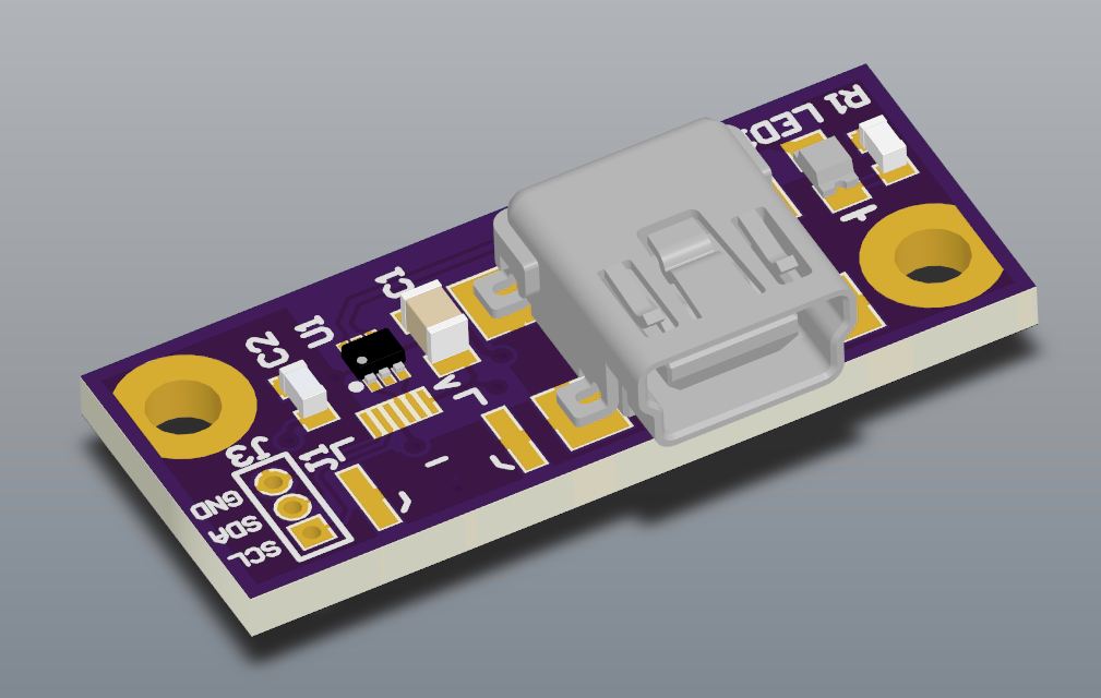
Mount pads look OK here.
But what arrived from the fab was this:
There aren’t supposed to be voids in those mount pads…
When I poured the rest of the GND polygon, apparently Altium attempted to connect to the inner Pad, and generated Polygon Cutouts surrounding it, which happened also to cut the Multilayer polygon. It didn’t show in the PCB editor, although it did in the Gerbers – but I was in too much of a hurry when ordering to notice. Oops. But so be it, it’s only the mount pads.
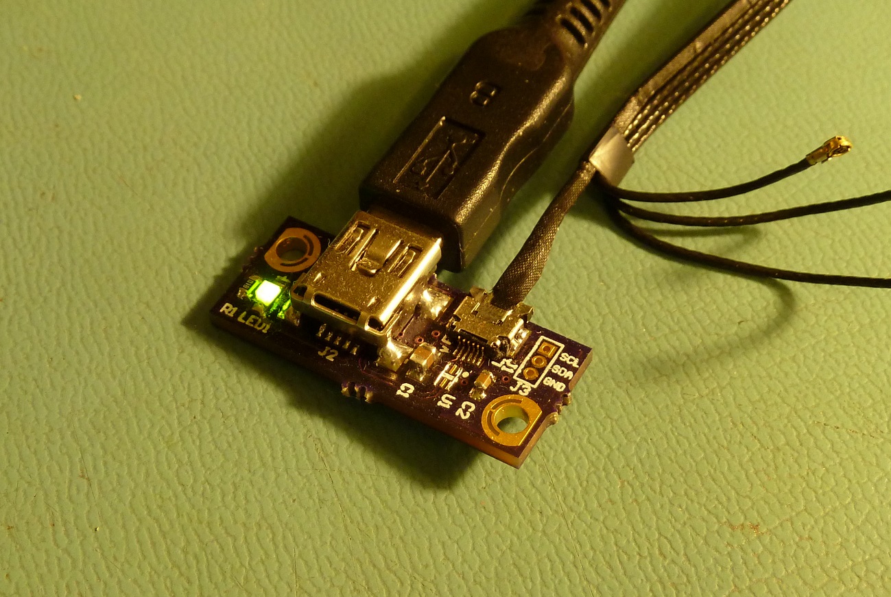
I then assembled the board, and with bated breath, plugged it into a USB port. And Hooray! The Device Connected sound sounded, and the camera showed up in device manager. But, strangely, the power LED was orange. I specified a green LED, I thought I placed a green LED, but it was bright orange. I checked the package to be sure but it was correct. It was then that I discovered a tiny short, and simultaneously learned that if you apply 5V directly across a 2.1V green LED, it becomes an orange LED. Neato! It also gets real real hot. But miraculously, after I corrected the short, which had caused the full USB voltage to appear across the LED, it returned to green and operated as normal. So I guess I can say, these OSRAM CHIPLED parts seem to be pretty hardy! I unfortunately don’t have any photos, but these parts are cheap, so buy some and experiment for yourself. Science!
After a few days the 4 layer board order deadline had arrived again, so (having not discovered nor corrected the pad issue) I re-ordered the board as 4-layer, this time adding a second transient suppressor for the ALS connector… because why not, and you can always short it with jumper wires if you don’t want to use it. So here’s what that looks like (note that I have fixed the pad issue at this point):
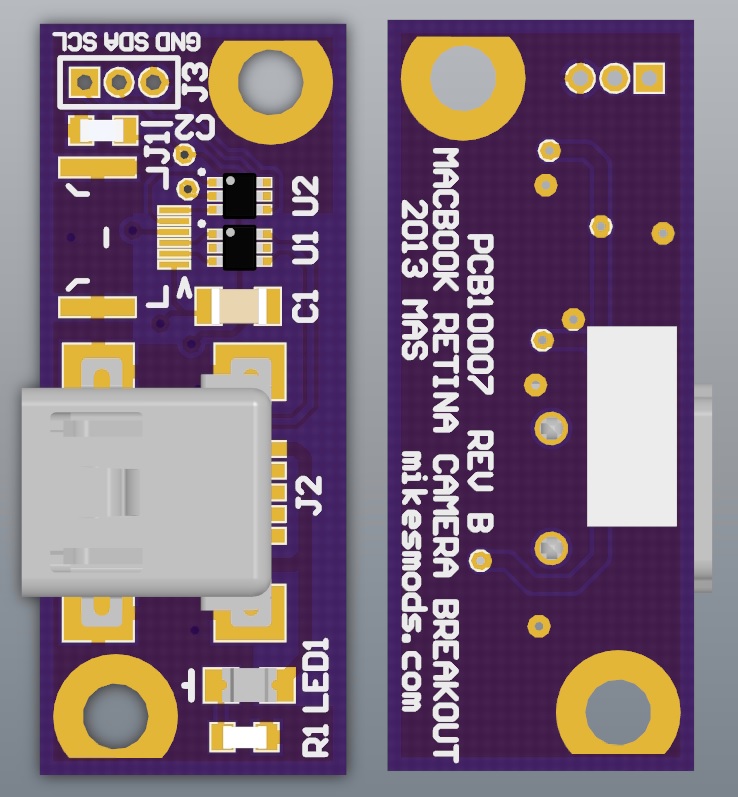
Yep.
I haven’t bothered to build this one yet, but it hasn’t changed significantly since the 2-layer version, so I suspect it’ll work fine. The files for this board can be downloaded here:
- PCB10007 REV B GERBERS (13K ZIP)
- PCB10007 REV B LAYERS (22K PDF)
- PCB10007 REV B STENCIL (1K ZIP)
- SCH10007 REV B (49K PDF)
Enjoy!
Main Controller Board
Now, the information you’ve all been waiting for. As I said on the previous post on this subject, I quickly threw together this board to get it in before the following OSH Park cutoff. As such it’s not perfect, but it is fairly functional (or so it seems from the minimal amount of testing I’ve done so far).
There’s a lot of new stuff going on on this board, as compared to my iPad board (on which this one is loosely based). Of course the panel output connector is different, because the panel is different. Also, though, the barrel jack has been removed, and a 2-pin shrouded connector has been added in its place. Barrel jacks, I finally came to realize, are just too damn big and expensive for a little cheap board like this. The new solution is less than a dollar in single quantities for plug, receptacle and terminals, whereas the board mount barrel receptacle was more than a dollar by itself, not counting wire mount plug. Plus the barrel jack tended to be the tallest component on the board, driving enclosure dimensions. It takes a bit more work to implement, but I still think this was a good change.
The dc-dc converters are new as well. The board contains two dc-dc buck regulators, both based on the AOZ1281 from Alpha & Omega Semiconductor. This part was chosen due to very low cost – about $0.90 in single quantities – as well as ample output current (1.8A) and acceptable input voltage range (3-26V). The board implements this part as one 3.3V/500mA converter and one 3.8V/1A converter, the former for processor, indicators and other functions, and the latter for the panel itself, which was investigated and found to run well on 3.8V in a prior post. It’s probably a 5V panel, in retrospect, and I may someday become ambitious enough to test it at this higher voltage, but for now 3.8V works.
The board shares the same Freescale MKL25Z128VFM4 processor as the iPad board, again due to cost to performance ratio of the $3 ARM Cortex-M0+ core. Sure, I could drop $0.50 and put in a MSP430, but I like the potential for other functions that the more powerful processor enables. I still need to learn how to program the damn things, but I digress. The other big IC on the board, the backlight driver, has completely changed compared to the iPad version. Whereas the iPad panel has 12 backlight channels at 20V apiece, the Macbook has only six channels but at some 52V. The LT3754 used on the iPad board only does 45V, so a new backlight driver is needed. Of the (relatively few) integrated boost converter / LED driver ICs, the best choice for this application seemed to be the Freescale MC34844A, which happily will push out 60V with appropriate configuration.
In the interest of keeping this post from being more than fifteen or twenty pages, I’ll leave the rest of the description to the schematic, but if anything is unclear please feel free to drop me a comment or email.
Again, this board uses 2-56 mounting screws, and again, I opted to include clipped pads. And again the boards showed up with voids in the pads. But this time, inexplicably, some of the pads did not have voids. They were all created the same way so I can’t quite explain that one yet. But one thing is for sure, I’ll certainly pay more attention from here on out. I built the pads for one of my boards at work with clipped edges as well, but this time used top and bottom polygons instead of one multilayer one. In this way the pads are slightly smaller in the internal layers, but on the other hand the polygons connect without issue, so that’s a small price to pay.
Anyway. Here’s the (99%) finished board, lacking only a fuse and transient suppression diodes in front of the USB port and DP connector:
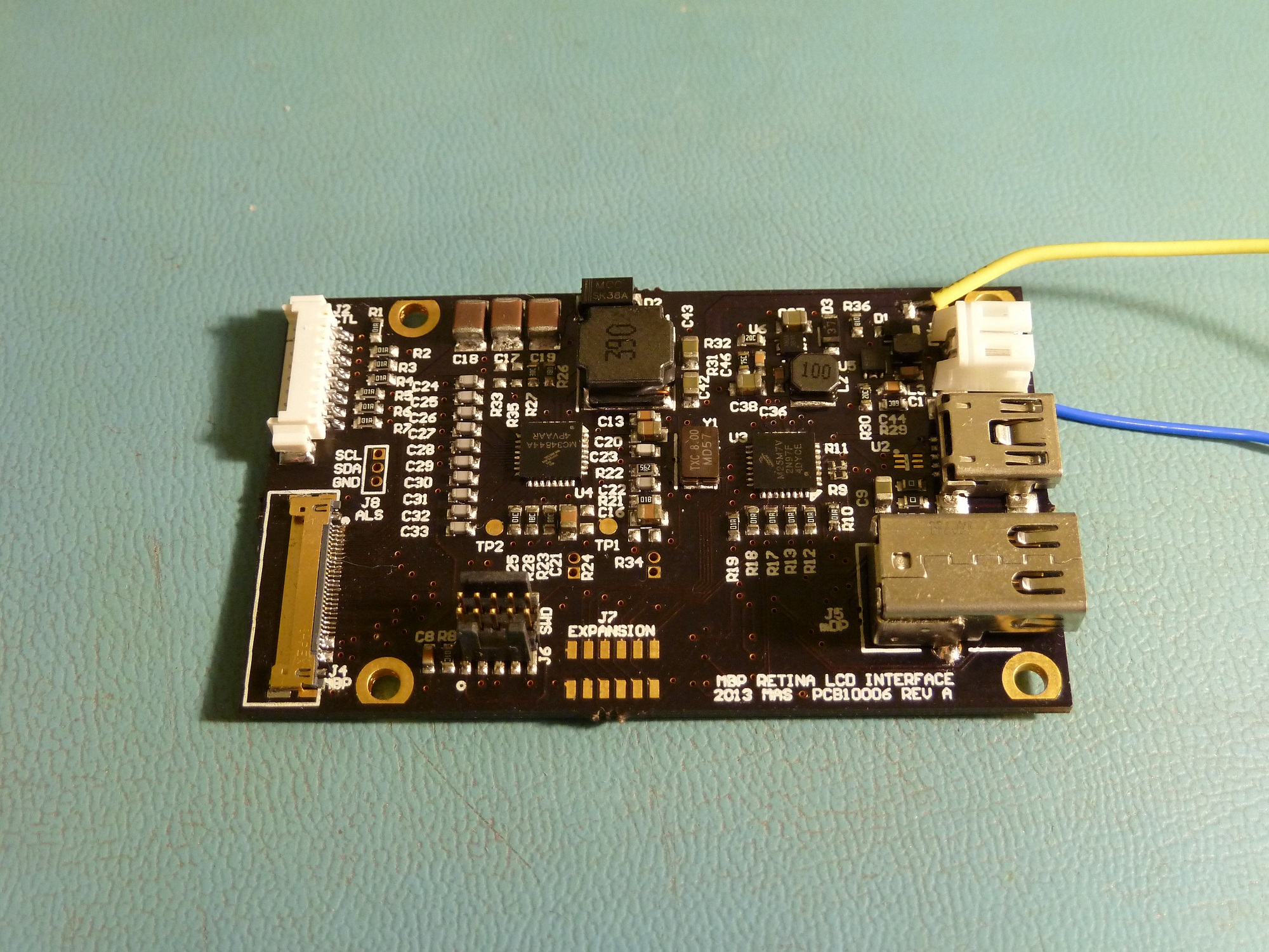
Top. Ignore the soldered-on power wires.
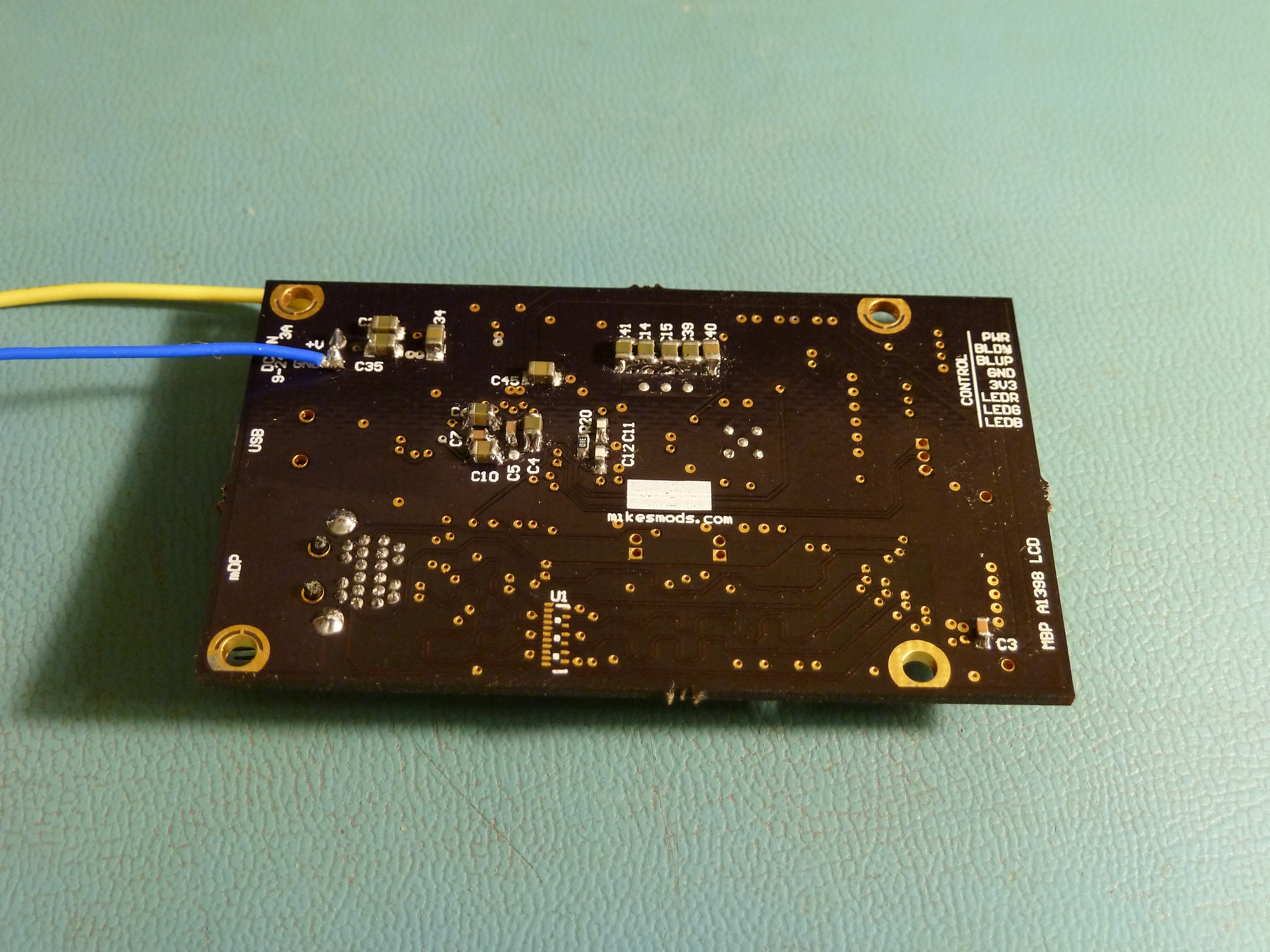
Bottom.
I’m not 100% happy with it – in particular, I suspect that my overzealous attempt to match the lengths of the DisplayPort lanes may have actually had an adverse effect on signal integrity as the traces have to bend a whole lot and come in much closer range of each other than is really recommended. But I can say that the board works like this, and I can’t keep from releasing something forever because I’m not 100% happy with it (or so my boss always says – “You can always fix it in Rev B”). So here we are.
Now, the processor has control over panel power and backlight on/off and brightness, so without programming the processor the board won’t do anything. So, still lacking much experience with the ARM Cortex-M0+ platform, I wrote a very barebones program that simply turns on the power and backlight driver for the panel, and additionally powers up the PWM controllers for the offboard indicator LED. So here’s the board documents, and the source to at least power-on the necessary systems:
- PCB10006 REV B GERBERS (76K ZIP)
- PCB10006 REV B LAYERS (107K PDF)
- PCB10006 REV B STENCIL (3K ZIP)
- SCH10006 REV B (103K PDF)
- TestPCB10006 (CodeWarrior project, 62K ZIP)
Holy cow, I just realized I never released the documents for the indicator/button board either! Well, let’s go ahead and do that now too. Here’s what it looks like:
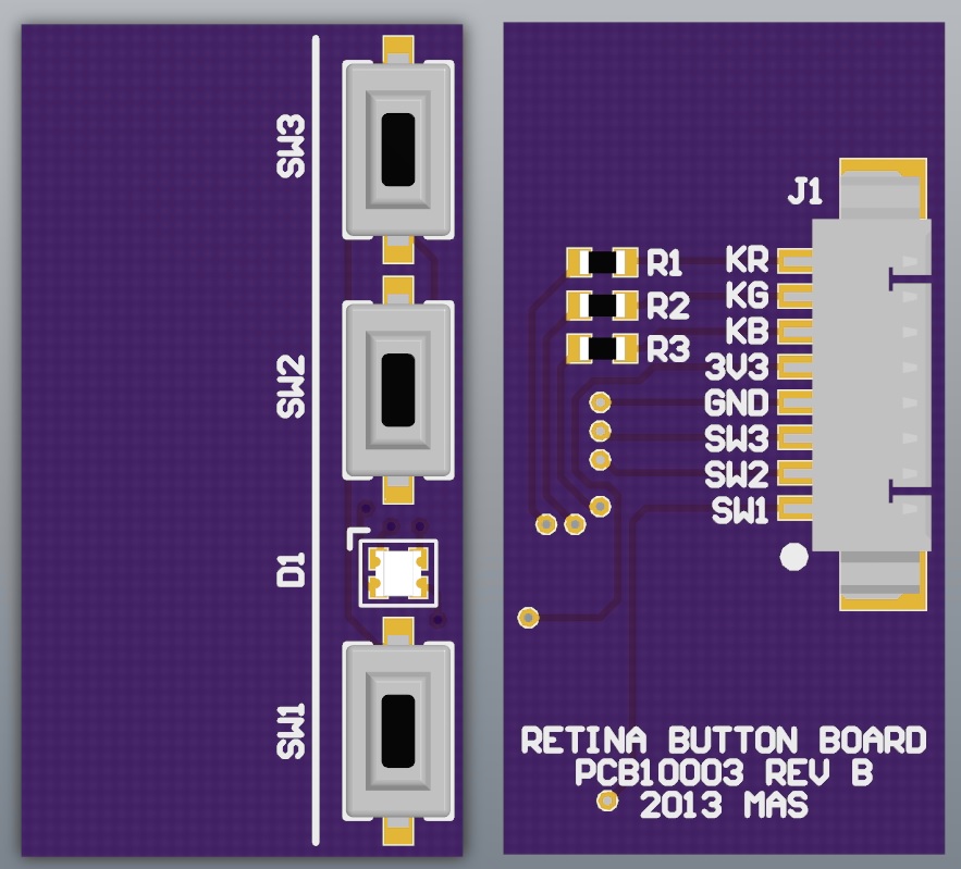
Pretty simple.
This board is designed to be double-stick taped directly to the back of a panel at an edge of your choosing (my preference is bottom-right) and connected to the main board via a wire harness. Some of the other controller boards out there with buttons onboard have very awkward button placement, so this is a slightly more expensive but much more elegant solution. The files for this board are attached here:
Whew. This has been a grueling post to prepare. Enough for now. Er, except for one last picture!
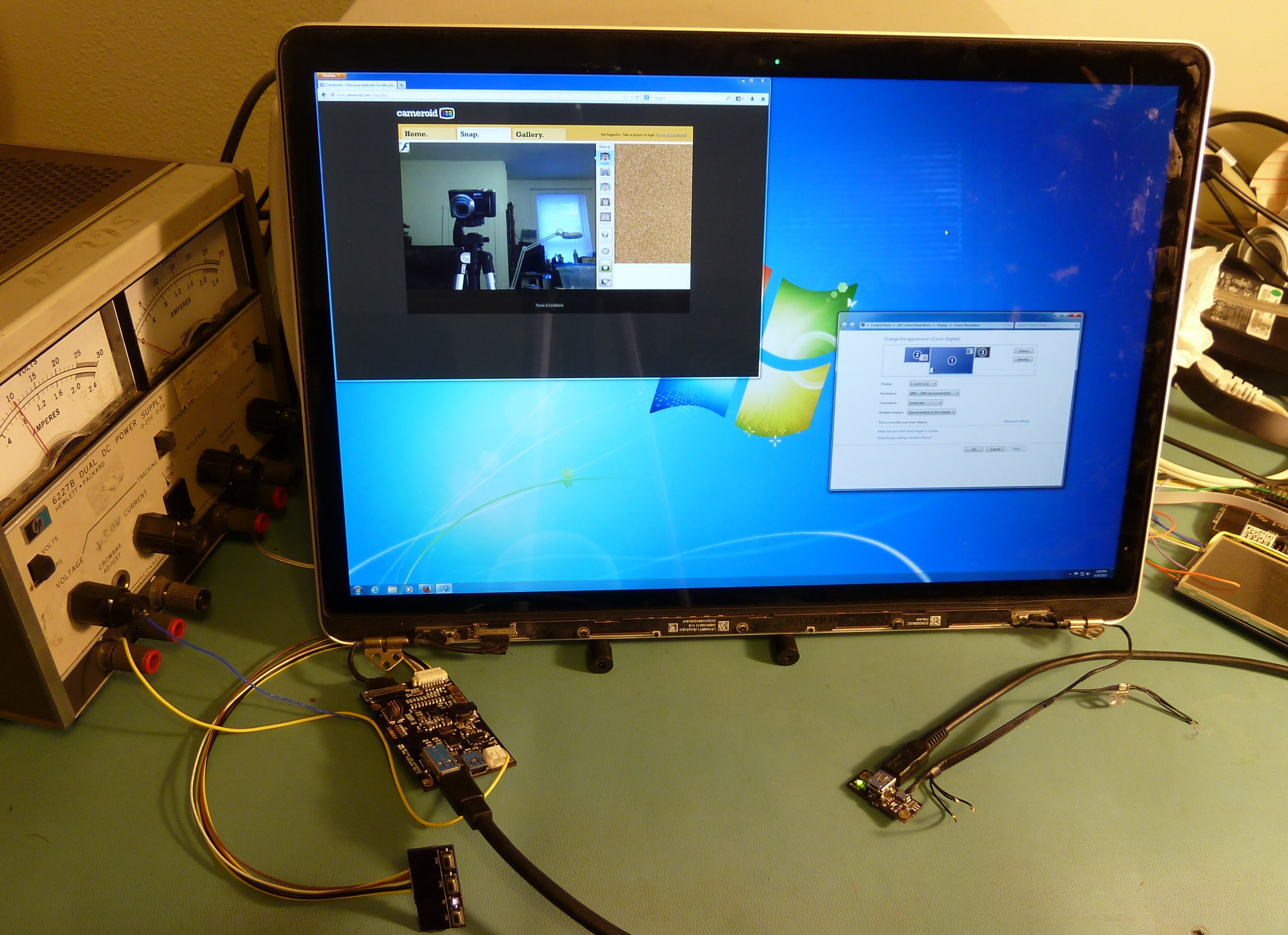
Woohoo!
Great Work on the Facetime Camera Breakout Board!!! My question is what application would you suggest I use to open the gerber and layer files with or alternately, how can I go about getting a Facetime HD Camera breakout board to test and try out? Your work has inspired me to educate myself further in PCB and Electronics design – I can’t say thanks enough.
The layer file is just a PDF, so you can see what the Gerbers look like without having to install (or for that matter, load) a proper CAM viewer. That always irks me, when someone releases a design but only as fabrication files, and I have to go load up the big-gun software just to see what the thing looks like. So that’s what the layers doc is for, and not much else (although I suppose you could use them to etch the two-layer boards, as they’re printed 1:1). If you really want to look at the Gerbers themselves, unfortunately a lot of the free software packages (Eagle, Kicad) don’t support that (to my knowledge). There are options, however: often the free software GerbView is noted as a way to do this, but also in searching for answers to your questions I found http://www.gerber-viewer.com/ which I loaded some of my stuff into and it seems to render it just fine. You of course can’t edit with that, but really you don’t want to be editing Gerbers anyway – what a mess that is. If I ever get my source files in order I’ll post them so people don’t have to go through that hellish process (can you tell from my tone that I’ve had to do this a few times before? 🙂 )
Now, how can you go about getting a board? Well, the easiest way is to go to OSH Park (http://oshpark.com/), upload the zip file of Gerbers and order a few – the Gerbers should already be set up in a format that OSH Park likes. They’re real cheap – 3 boards for $5 shipped – and the components aren’t pricey either – or you could even solder on a cut USB cable which we all have hundreds of around, and no-load all the rest of the components, and it’d probably still work (er, so long as you short across the transient suppressor IC). Now, getting the camera connector is going to be the most difficult part, because I honestly don’t know where to get it or even what the part number might be. I got mine from a Macbook Air camera processor baseboard, for which I paid about $6 (not terrible for qty 1 of an exotic connector). You have to be cautious of exactly which assembly you buy, though, because Apple has used a whole bunch of different connectors for their camera assemblies over the years. I looked at several boards and identified one as having the correct connector from the seller’s photo before I bought it – you can see photos of the board I bought in this post: http://mikesmods.com/mm-wp/?p=340 .
Now if your question is “can I buy an assembled board from you”… that one’s probably “no”, simply because I don’t like having to rely on ripping connectors off of eBay camera modules to build these things. If I ever find a source for new connectors, though, I’ll happily rethink that.
You’re very welcome for the inspiration 🙂 I have been toying with electronics for practically as long as I can remember, and it continues to be a field where the more I learn, the more I find I don’t know and want to learn. If you need any help as you delve into this stuff, please don’t hesitate to drop me a comment or an email.
Hello! Do you plan to sell this boards? I’d like to buy one for my damaged laptop assembly if possible. Thank’s!
To tell you the truth, there’s not been a whole lot of demand for them yet. The initial costs I have to incur to sell these (bulk component purchases to make them affordable, stencil since I refuse to manually paste any more of the damn things) have to be offset by projected sales of the board, and right now that’s not happening. Plus I’ve got a plan to switch out some components once I get ahold of a healthy enough source of the alternative, so I’d want to do that before I invest in a stencil or production-quantity boards.
In summary, unless you’ve got a few friends, I don’t have plans in the short-term. But keep an eye out, because it may happen sometime in the future.
Have you seen this?
http://dp2mbpr.rozsnyo.com/
If your version would cost half of that incl. shipping I’d be happy to order one even without a camera breakout.
Hmm. Actually, Daniel Rosznyo helped me out a bit as I worked through the reverse engineering process, as can be seen from some of the early posts on the subject.
The BOM cost of $150 does seem a bit steep, though, considering I calculate the BOM cost of my boards somewhere around the $60 mark, not counting ancillary costs and manufacturing fees.
The problem is and has always been that it’s only economical to produce these boards in batches larger than one. Whereas on the iPad unit it might take me two hours to build, test and package an assembly by hand (since I don’t have stencils), this one easily took six or more when all was said and done, not counting testing time. There’s no price I can reasonably charge to make it worth my while to spend six or eight hours pushing solder paste around with a toothpick. This is of course not a problem if I have a solder stencil, but for the very small pitch of some of the pads on these boards, I can’t use a cut-rate stencil fab and need to purchase a professional framed stencil, which usually cost upwards of $100 and can approach $200. So I need to sell “a few” boards in order for the cost to be properly amortized across each, to avoid having to charge each person an arm and a leg. Right now that number is around ten or fifteen, and I don’t have that many interested parties.
Find some friends and we’ll talk 🙂
Would OSH Stencils be an option for this?
http://www.oshstencils.com/
Huh, I hadn’t heard of OSH Stencils, thanks! Unfortunately, these boards typically cannot use a Kapton or Mylar stencil, because the webs on some of the required connectors’ footprints are so narrow that the laser cutting the material typically just melts it – or even if not, all the tiny threads of material would likely tear on first use. I’ll drop them a line and see what they say, but I wouldn’t hold your breath…
Feel free to give us a try Mike, I think you’ll be surprised at the precision we can attain. We have a very different process for our Kapton stencils compared to what you may be used to. Shoot me an e-mail if you have any questions.
One of our customers recently posted this, for reference. http://imgur.com/dIHKSOK,KQMr1QV#0 These are .2mm apertures, and .5mm spacing between them. If you click the second image (a competitor product) you can see a very clear difference. We do a lot of ultra fine pitch work, and have had great results. If this isn’t sufficient, hang tight, we’re going to announce some new material options by the end of the year that may suit your needs if our Kapton solutions aren’t a fit.
Hey, thanks for the input. Those apertures do look very sharp, but they appear to be rounded as if they are made with a single laser kerf, is 0.2mm the smallest that can be cut?
For comparison’s sake, my Simple iPad board uses 0.28×2.40mm apertures on 0.50mm pitch (web thickness 0.22mm) and my Macbook board uses 0.20×1.20mm apertures on 0.40mm pitch (web thickness 0.20mm). It looks like you can cut the apertures, but what I’ve been told by other vendors is that it is unreliable to cut with such small webs since the laser tends to melt the material, is that not a factor with your process?
I guess what I really want, not just from OSH Stencils but from all stencil vendors, is minimum aperture dimensions and minimum recommended web thickness for the material and process used. It’s so hard to get that kind of information out of vendors – I understand it’s hard to give an accurate number due to some dependence on the web length and surrounding geometry, but it’s so hard to get a good feel for what’s feasible and what isn’t!
The rounding is the users design, not an attribute of the laser. We cut exactly what is sent to us. This customer just happened to design his board with rounded edges on his ICs and all his pads.
I understand the frustration with vendors giving exact specs, and that’s largely attributed to the inconsistent nature of how they handle their cutting. I don’t have exact specs to release either, but that’s because I haven’t sat down and made the effort in determining the true capabilities, but we haven’t had a single design to date (knock on virtual wood) that we haven’t been able to cut to meet a customers needs.
If you want to give our stencils a try, feel free. If you are unhappy with the results, we’ll make it right to your satisfaction.
I may just take you up on that, as soon as I get some time to prepare the files 🙂
Can the camera breakout board be use with almost all old and new macbook displays or just the new ones like the 2011- 2013 models ?
Electrically, the camera breakout will work for any of the recent Macbook cameras, since they have had a USB interface for at least the last few generations. However, Apple has a bad habit of changing connectors from one model to the next, so it’s quite likely that the board may be mechanically incompatible. Is there a particular camera model you’re interested in? I have some docs on Apple hardware that might give us a better idea.
i was thinking the 2011 or 2012 model. the imac camera also interested me but have a different connector , wonder if its have the same pinouts tho
Sorry about the delay. I will try to look into this tonight.
no worries , take your time
Hm. As it turns out, I’ve only got information on units made before 2010. If you can find a high-res photo of one you’re planning to use, it might be possible to make an educated guess one way or the other based on that. Otherwise, sorry I can’t confirm anything for you 🙁
i couldn’t find any of the newest models or the 2012 models, even ho i thought i saw one last week, just cant seem to find it anymore.
Great job!
If you would ever consider taking orders for the board, count me in!
Thanks! I’ll keep that in mind 🙂
Please do. I’ve perfectly good panel laying around, gathering dust but lack the skills and tools to assemble the board myself. Those QFN packages are just beyond me.
There is one other option that comes to my mind: I don’t suppose that you take requests, but would it be possible for you to put together OSH-Park-compliant design of a board with only the DP pass-trough in place and inputs for external power supply (with optionally some feedback to the PS, that there is in fact something connected to the DP)? That way I could try going crazy with some less portable, but doable PS design. With my luck, I’m afraid that I would struggle with the design for quite few iterations before I get something done without breaking any rules. Not to mention that the wait alone would probably kill me ;). I hope, I could manage soldering the sockets in place, if not for the first time I would have 3 tries in a price of 1.
I’ve had several requests for a simpler board for the Macbook recently. It might be time to consider designing one of those… I’ll add it to my to-do list, but I can’t tell you when I might get around to it – there are quite a few projects in line ahead of it at the moment.
No pressure. Whatever you come up with: be it simpler* board or one that I could order from you directly I’ll take it. Once again: great work and I see that saying that you should keep it up is really pointless because you are just like that Energizer rabbit.
*something not requiring an oven to bake 😉
On “not baking”… That’s tough, because the Macbook mating connectors are just such fine pitch (0.4mm) that it’s difficult to hand-solder them. It can be done, but you’ll need a magnifying lamp, tiny solder, a very fine iron tip and a steady hand. I find it easier to reflow process them, because if you screw up paste application, you can just wipe it off and do it again, no permanent damage. But if you hand-solder a bridge in between those pins, getting it out can be a very frustrating process.
Nice work! Count me in as a very interested customer for a board or two.
Will do 🙂 The numbers are starting to add up…
Why don’t you start a kickstarter for this? You would definitely receive the funding you need to get it started!
Eh, Kickstarter. The problem with Kickstarter is that it pushes this stuff from ‘hobby’ to ‘second job’. Well-run Kickstarter campaigns need set schedules, regular updates, timely communication. I can’t guarantee some of those things without devoting more time per day to the project than I really want to (or can).
It’s never been a problem of funding… money just can’t buy free time. Well, it could if I quit my day job, but I don’t think I want to gamble on that!
Hello,
Please, let me know if you decide to make some PCB for sale.
I may be interested in purchasing one.
Actually, I would be interested in interfacing a 13” retina display (LP133WQ1-SJA1).
Do you think it’s easy to make changes to the electronic components of PCB10006REVB
for achieve the purpose? I think that the two panels differ only for the LED load.
I haven’t looked into working with the 13″ yet, but they are quite similar so it should be trivial to do so. But don’t quote me on that, I haven’t actually looked into the nitty-gritty of it all – and Apple loves to kill cross-compatibility by changing pinouts between products. I think I’ve got a specification document on that panel, so let me dig into it a little deeper.
Thank you for these posts and inspiring the reverse engineering of this. I was just thinking about such and adapter board but I see you and a couple others have already created them. I’ve enjoyed the read through your stories.
Do you know, would the adapter board work on a MacBook Pro Retina to drive an external display at 1920*1200? The MBPr spec states external displays at up to 2560 by 1600. Being the external display is physically 2880 * 1800, I wasn’t sure if this would be a problem. Boy I’ve been dreaming of small, high resolution external displays and I may finally have a solution.
I actually don’t know… I don’t have a MacBook to test it with. The board itself doesn’t mangle the signal at all, it’s just a passthrough – and as such should support a practically infinite resolution. But whether the MacBook GPU hardware can handle it, I don’t know, sorry!
Thank you Mike for the response. I see how the board is just passing the signals through. So perhaps my question is more generic and along the lines of what happens with a high resolution display, one with more hardware pixels than can be output by the laptop, is connected to the laptop. I imagine it will work at the lower resolutions, but it has been a while since I’ve done this. On to googling, this is basic enough question, thanks for helping rephrase the question and the inspiration from your work.
Hello,
I found this HDPI LG panel: LP129QE1-SPA1.
It is used on the ‘chromebook’ device. It is a 12.9” display with a resolution of 2560×700.
It found my interest because the datasheet can be easily found on the WWW
and it is very cheap compared to the 13” Macbook Retina.
I actually have one of those panels – t’s been on my ‘to-do’ list to build up a board for it for six months or more. Personally it’s a lot more interesting to me than all the other high-res panels because a) it’s a more reasonable size to do real work on than the tiny iPad panels and b) it can be found outside of full laptop lid assemblies unlike the Macbook panels. One of these days I swear I’ll get to it…
I only read the topic on overclock.net and got panic, seeing you hadn’t wrote there since last year! O.o
But it seems you are still breathing and building epic things, so please, please, please keep that Chromebook Pixel display in mind. I don’t know why, on 42 fu***** sites, noone seems to be interested in that epic piece of technology. :`(
I would order one or more of them today if you told you could build drivers (and ship them to Germany :D) in less than a month. Thank you for efforts from all, who don’t understand anything of PWM, eDP, LVDS, HDCP, DPCP and those other fancy words I now have read until 7am O.o The topic is just too exciting….
Oops, I’d all but forgotten about that thread. Time for a visit…
Yeah, it’s high time I build up a controller for the Pixel panel. They’re even down to the cost of the iPad panels on eBay – and so much better, in my opinion. Now if only I had the free time…
Shouldn’t be all to hard. If you took a PC motherboard like the Asus Q87T, then all you would need on an intermediate board would be a Freescale MC34844A, and you could include a connector for both the Pixel LCD and the 15″ Retina. The motherboard produces 12v or 19v DC for the MC34844A and even provides a PWM Signal directly from the ACPI (OS). I’m in the process of designing some boards.
Hi!
I’ve actually already built a controller for the Chromebook Pixel panel. It looks great! I’m going to have to document it at some point..
Please! No one has documented how yet but plenty have tried and given up. You’d be doing everyone a big service.
Looks interesting despite the odd AR. Just hope that it’s not one of those pentile-like “miracle” panels. I’ve spent some time evaluating image quality on a notebook equipped with the LTN133YL01-L01 (13.3″ 3200×1800) and trust me it is dreadful. Apart from the color representation issues, which I don’t usually pay much attention to, the resolution spec. is just a nasty hoax played on the retina-crazed people. Just try displaying some white text on blue background or vice versa and you immediately start to wonder: “where half of my pixels have gone?”
I work mostly with displaying tons of text (don’t really care for font quality as far as it’s readable: source code mostly) and I think that apple just hit the right spot with their 2880×1800@15.6″. Anything more dense makes me just go pixel-blind and I start to scale the fonts. It appears to me that the next usable and worthwhile solution would be some 4k panel in a 17-19″ realm. Anything above (DPI-wise) just seems plain waste of (pixel)ammo.
Saying all this: hey Mike get your act together and start taking orders for the MBPR board ;).
Pentile on a notebook? Ick. Hey, that’s not the panel from the Samsung Ativ Book 9, is it? I was really excited to hear about that when it was announced, and I haven’t heard anything since.
I need to fix/finish the firmware before I will feel ready to release the MPBr board. And to do that I need to learn some major ARM programming. Unless you happen to know a programmer with too much time on their hands…
Yep. I afraid that it’s all over the place: Samsung, Lenovo, Eurocom, Clevo all have models build around this panel. One can hope that it’ll drive the cost down, but than again I’m not quite sure it’s worth it. I mean: it’s ok (works as advertised @3200×1800) when you display monochrome text on it. But the things go south really quickly when you start to employ something as cutting edge as syntax highlighting for instance ;).
Either way the DPI is bit too much for me to use it comfortably. Maybe for viewing images it would be fine (lower spatial frequencies) but for (colored or not) text it’s just unusable.
As for the programming part: if it’s got a C compiler I could give it a try. I’m afraid that I don’t know much about ARM assembly, but I did a fair amount of 8051 and x86 asm programming back in the day. But it’s just talk the talk, as I’m not capable of building the board on my own and I can’t even start to imagine how to remote debug this sort of stuff.
Being like da Vinci is not as easy as it used to be I suppose.
Hi Mike, any of the Retina boards for sale? Would need one.
Not yet… but there has been an awful lot of interest lately. Maybe a link got posted somewhere. In any case, it’s climbing higher on my priority list by the day, but it’s not quite at the top yet. You’ll have to be patient a little while longer, sorry!
Hi Mike, it’s very interesting to read about your work. I’m also interested in 3 or 4 of the MBP Retina boards if you should ever sell them.
Best regards Kristian
Thanks! I do think I’ll eventually end up making some boards to sell, but probably not in the immediate future.
Hey – Did you ever try setting the refresh rate above 60hz?
ok i am going to go out on a limb here would anyone know where i can get a controller board for LP173WF2-TPB2 i have a broken m17xr3 and would like to make the LCD an external montior and noone and i mean noone has the controller board for this model which i find really interesting being that its a couple of years old already..and some people advertise that they have universal ones but before i buy one i would like to make sure.
I also want a small 120hz screen for my gaming machine (a) for portability/taking it to LAN parties and (b) because I have tunnel vision and don’t really benefit from larger screens. I know Mike had started looking at the -TPA1 version of this panel a while back – he was going to use it with the MBP retina controller but had some trouble with the cabling. I wonder if he’s had a chance to look at it since then.
Very nice project. Please don’t stop. You are very good at this I absolutely admire people with such skills and joy at their hobby.
Do you think it is possible to modify the circuits of a non retina Macbook to run a retina Panel?
It depends. A lot of the older Macbook non-Retinas used LVDS instead of DisplayPort to drive their displays; if this is the case, then it is non-trivial or impossible (depending on configuration) to convert one to the other. I’d have to do a little digging to give you a more concrete answer.
Hi mike, a bit offtopic, do you know if the keyboard/trackpad from a macbook pro retina can be modded to usb?
Regards Kristian
@Kristian! Yay! Trackpads and keyboards! I’m working on that right now, I have some breakout boards designed. I can send you what I have if you’re interested.
Tim
Hello Mike,
I’ve already ordered almost all components. However, I am not sure about the crystal/oscillator to buy.
Please, may you provide me with the parameters of Y1 that you used. In particular
I miss the load capacitance.
Thanks,
Massimiliano.
I know this an old thread, but any chance you could add an outline to the “STENCIL” files quick??
OSH Stencils prefers an outline for the stencils. Not a requirement, but wanted to give them a go and not sure of the consequences of not having an outline . . .
Thanks and best of luck on the house and lab!
Bill
Hi Mike,
This is a awesome and inspiring project! I’ve learned much, and have been inspired to learn more.
I don’t quite think I’m able to build my own yet, but I’m not adverse to trying!
Thank you!
If you ever do get around to building a batch of these for sale, please let me know. I would buy 3 to 6 of them. (I have a project in mind!)
Regards,
Joe
Thanks, will do!
If you ever sell the board, Im interested in buying one 🙂
Please notify me
Will do 🙂
Very nice!
Thanks for this info.
I want a 16:10 monitor for my diy laptop, having a modern beautiful display, with cam in it, is gonna be awesome.
If you do happen to sell a controller board, hit me up. 🙂
Hallo Mike,
impressive work!
By accident I purchased an LG lcd for my macbook pro (mat screen so non retina)
After my screen didn’t want to lit up anymore, I had my laptop checked in an official apple repair center.
They could restore it for 700€. I chose to restore it my self, ordered a screen online and recovered my laptop from the repair shop. I come home, start up the engine, and, quite amazing, the screens functioned as before…
So now I have this new lcd, and if your board for the retina is compatible and available I ‘d like to order one.
If not I might experiment to assemble the board, enthousiasted by your work and posts.
Well done!
tom de with
brussels
What I’d really like is to do is use an MBP Retina Display as an External Monitor via mDP/ DP . HDMI is a bonus.
Besides the board you designed and I can send those files for a Fab, what other parts would I need?
I do not mind scrounging the Fleabay for the pieces and Soldering them on the board.
Is your design capable of this? PS: I was wondering why there is talk of USB cable (for power??) and Camera (what does it have to do with DP)?
Sorry, I was reading and just got lost. I wouldn’t mind the effort in assembling/ soldering the pieces together as long as I can get clear on what pieces are needed – Item list.
I just downloaded the last 3 linked files. Would that be enough to save?