After discussion with commenter Eva in the last part of this series, i was motivated to make some progress on the investigation of the iPad 3 digitizer. Based on leaked schematics for the iPad mainboard assembly and on the physical digitizer itself, I have mapped the physical pins on the digitizer FFC to functions. There are 40 excitation pins, 30 sense pins, three grounds and a SHLD pin of which I have not yet determined a function. Normally SHLD means shield, but it’s being fed into a processor input so that doesn’t make sense. I will continue to investigate.
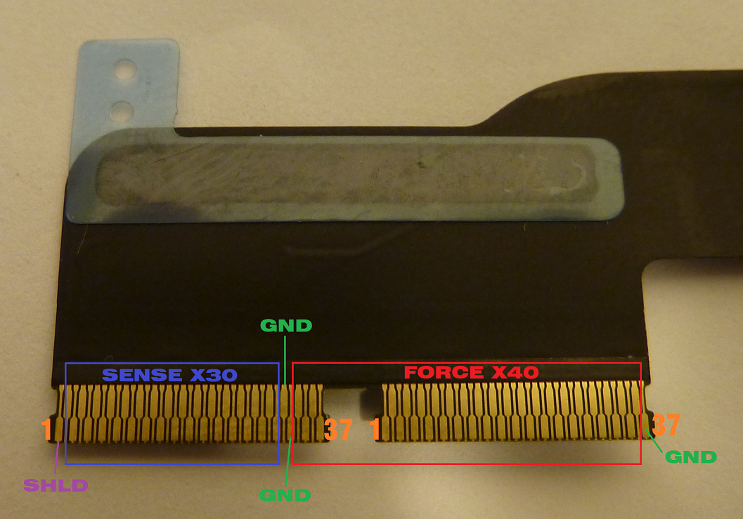
Layout of the pins on the iPad 3 digitizer.
The leaked documents also indicate that the proper mate to these are Molex 502250 series connectors, the same series as the one used on my DisplayPort boards for the eDP tail. But contrary to the 51-pin version, this one is not so easy to get ahold of. As I noted in the previous post on the digitizer, the 503566-3700 is a close alternative, but it looks as if these FFCs are just too wide (11.7mm) to fit in them (11.4 +/-0.05mm max). There are not a lot of alternatives though, so if worse comes to worst I may end up trimming the FFC to fit – as you can make out in the above photo, there is a small amount of tab with no contact at each edge, and without this the connector easily comes in at under 11.4mm. Also of note, the distance from the edge of one connector to the edge of the other is 13.5mm.
I have done all I can do with the digitizer by inspection alone, and at this point can only advance with it electrically. To aid in this I have drawn up a simple breakout for the digitizer. As I was not sure what my end application would be, I included provisions for connection either to a breadboard directly or to another board via inexpensive 40-pin IDE cables. The FFC connectors are on the bottom of the board, since the contacts of the digitizer face up when the tail is unfolded and the connector chosen has only bottom contacts (the 502250 series has contacts on both top and bottom). Not ideal, but workable for the short-term use that this board is designed for.

A simple breakout for the iPad 3 digitizer.
Each position is labelled on both sides with its function to the best of my knowledge. Dimensions of the board are 0.9″ by 4.1″. Production of this (2-layer) board at OSH Park costs $18.50 for three pieces. Populate J3 thru J8 with 0.1″ snappable header strips – omit J4 and J7 for breadboard use, and omit J5 and J8 for IDE cable use. The mount pads are sized for 2-56 screws.
I have ordered a set of these boards and plan to experiment with them a bit, so you may want to wait until I troubleshoot everything. If you are impatient, documents for the digitizer breakout are below:
So then, now that we can connect to the panel, how do we read touches? That part isn’t quite so simple. If the documentation from the iPad mainboard is to be trusted, 40 independent outputs are generated and sent to the panel in sequence to 40 horizontal electrodes, and 30 vertical electrodes pick up the signal when coupled into them by a conductive mass (e.g. finger) on the surface. In the first part of this series I counted 41 squiggly horizontal lines and presumed these to be the electrodes, but it turns out that the sensitive area is between the squiggles, resulting in 40 driven rows.
The methods for driving and sensing touch position are a hot area of development in industry at the moment, and the big companies are all hush-hush on their analog frontend design. But we know generically how Pcap touch should work, and we can take a guess from this and by examining how Pcap is implemented in devices. For instance, we know that Apple uses three main ICs to drive the touchscreen – a driver to generate the output to the panel, a receiver of the signals produced by the panel which incorporates an analog-to-digital converter, and a processor to interpret the ADC data. One popular method of Pcap sensing is to use the changing capacitance to shift the frequency of a relaxation oscillator, then use a frequency to voltage converter and finally an ADC to sense this capacitance. Given the structure of the panel and supporting circuitry, it seems reasonable for the panel to be read in this way. A couple of links that provide information on mutual Pcap: http://ww1.microchip.com/downloads/en/DeviceDoc/93064A.pdf, http://www.walkermobile.com/SID_2012_Short_Course_S3.pdf.
I believe it is unlikely that a hobbyist would be able to get ahold of the particular solution used in the iPad – in fact, as at least the receive and processing ICs are made by Broadcom, I’m positive it is impossible – and it is almost as unlikely that there will be an off-the-shelf controller with the proper number of channels that a hobbyist can buy in reasonable quantities. I therefore plan to implement a solution using generic hardware – simple programmable logic and/or MCUs. This way cost and minimum buys aren’t problematic. But that architecture is a topic for a later post, this one has gone on long enough.
<< Previous post in this series … Next post in this series >>
Do you want some help? If you sent to me one of the boards that you make to analize the iPad 3 digitizer. I am could help you to make a prototipe board that make possible use a iPad touch in future projects. I have problens with iron solder, I couldn’t make one of these by myself.
Thanks,
Andrei
Hi,
Do you have spare breakout board and connectors?
I would like to do my own testing. Willing to share results of course.
Unfortunately I sold my last extra board a while back, sorry! The Gerbers are posted if you’d like to order your own though.