I would say I’m pretty good at hand soldering. I can solder TSSOP and QFP pin by pin, and I work with 0603 size parts on a very regular basis. Unfortunately, industry has decided that 0603 parts and exposed pins are wasteful in space, and many really neat parts come only in QFN or BGA, and next to these, 0603 parts are absolutely gigantic. I thus find myself wanting a way to process boards with no-lead and micro-scale parts. At this size it’s pretty much reflow soldering or the highway. The company where I work has a nice six-stage production reflow oven, but I can hardly go asking them to fire that up whenever I need something made, so I would like to have a solution at home to do quick-turn work on my own.
There are plenty of projects on the Internet that document homebrew reflow systems. Some are built on electric skillets, some in toaster ovens, some in custom made boxes, with varying amounts of complexity. But I have found that most homebrew designs lack the advanced features found on “real” reflow setups. Proper profiling is desirable – that is, not only getting it hot enough to melt, but actually following the manufacturers’ specified ramps, which should lead to more reliable boards. The ability to sense temperature at the board or high-mass board components and provide provisions to optimize the ramp thereafter would also be nice. Semi-automatic cycling would be good, to press one button and come back in ten minutes to a finished board. And all of this should be possible without the unit needing to be tethered to an external computer, thereby keeping the footprint small.
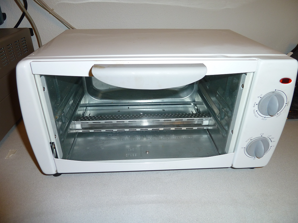
Here is the (un?)willing victim, an el-cheapo Wal-Mart toaster oven.
Similar to many designs, my plan is to base the unit on a basic toaster oven – in this case, a 1000W unit with two quartz heating elements, model TO-88, originally from Wal-Mart but in my posession via a dumpster. There is nothing particularly special about this toaster oven, and any similar design could also be used.
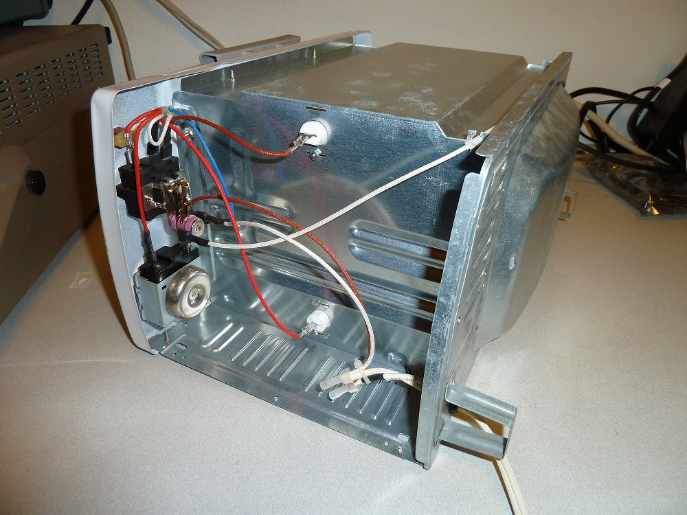
Inside the toaster oven. Not much to it.
The inside of this unit illustrates exactly how cheap it probably was. It makes no effort to insulate the cooking chamber from the outside world, which must make it very inefficient as well as hot to the touch. The innards are all 28 gauge sheet steel, which has gaps where it was bent to shape. The control system uses the (high) ambient temperature directly outside of the cooking chamber to regulate cook temperature in the box; how it achieves any sort of temperature accuracy is boggling (it might not be remotely accurate; I really haven’t tested it). It’s electrically pretty simple – hot lead in series with the timer, in series with the thermostat/element selector switch, in series with the two elements (in parallel through the selector switch), and out to the neutral lead. I have picked up a couple of other toaster ovens and there are more elaborate control systems than this, but I plan to rip all of this out so it’s not important how complex it is.
I will need to do a little testing to determine the characteristics of the unit – primarily, maximum heat rate, and maximum cool rate when elements are disabled. I suspect that 1000W is enough to heat the board quickly enough to conform to proper reflow curves, but that despite its lack of insulation the unit will not be able to cool off fast enough to meet the profile. I am therefore tentatively planning to circulate air through the box with a small blower at one end, and vent it out the other. By controlling fan speed and heating element duty cycle, I should be able to very quickly and accurately control chamber temperature. I will also leverage the blower to make sure heat is evenly dispersed throughout the chamber to prevent hotspots. To reduce the power required to run a board and the heat at the exterior of the box, I will insulate the chamber where convenient to do so (likely inside the outer casing, at top, left and right) with fiberglass mat.
The existing controls will be removed. The top control (thermostat) will be replaced with a main power switch, and the bottom control (timer) will be replaced with a neon indicator of heating element power. The blower will be housed in the plenum where the controls were, and will be ducted into the chamber. Hopefully this will allow it to be far enough away to prevent the (plastic) blower from being damaged by heat. So long as the fan keeps sucking cool air, I think it should be OK.
The main control circuitry will be housed in a new control panel affixed to the side of the unit, which will be built in a plastic project box (Hammond RP1065). The box will contain a Crydom D1225 solid-state relay (I already purchased this on eBay for this purpose), heatsunk out the back. It will also contain a custom board which will serve as the brains of the unit. I am planning to use the same 32-pin Freescale Kinetis L2 processor as the iPad screen controller. This will talk to two Maxim MAX31855 thermocouple-to-SPI converters and in turn to two K-type thermocouples which can be affixed to a board in the unit. Front panel control will be achieved via a 1.8″ SPI LCD and a few tactile switches. The unit will be able to take input from USB, front panel and/or SD card (not sure which combination will be implemented).

First concept for the controller for the reflow oven. The PCB isn’t shown as it hasn’t yet been designed.
The oven, SSR, fiberglass mat, scrap sheet metal, blower, and hardware are all in house already; the LCD and thermocouples are on order. Most of the remaining components will come from Digikey as soon as one of them comes back in stock. I am feeling good about this – it’s about time I got around to building it. More later.