Weekend Project: Determining Operating Parameters of a Memory Core

Hello again, and my apologies for the long time since the last one.  Today I’ve got a quick topic to discuss, and although it’s fairly obvious, I don’t think it’s documented elsewhere online.

I’m working on a project for which I’ll be building a fairly sizable core memory array (see here for the first post on this topic, which covers the construction of a small demonstration array).  As noted in the original post, it is simple to address a huge number of cores in an array because the core material will only change magnetic state when a sufficiently large current is passed through it; any smaller current will leave the core in its initial state.  Thus, by passing only half the necessary state change current through the core through each of two wires, and by ensuring that no two cores have the same two wires passing through them, any individual core may be selectively read from or written to based on the set of wires that are energized.

But how much current is necessary?  There is no standard (to my knowledge) that says all memory cores require x milliamps to flip.  If you buy a set of random cores on eBay like I did, this is a question that needs to be answered before any further design work can take place.  So I tried a few methods, found some things that worked and some things that didn’t work so well, and decided to share my results.

First, recall from Ampère’s Law that a current flowing in a wire creates a circular magnetic field around that wire.  If the wire were pointing toward you and the current flow was coming toward you, the magnetic field would be counterclockwise – or using the common “right-hand rule”, if you wrap your right hand around the wire with your thumb pointing in the direction of the current flow, your remaining fingers determine the direction of the field.  From the right-hand rule we can also see that if we want the magnetic field to reverse – which we need in order to change the data on the core or to read out the data that is there – we would have to flip the flow of current so it goes the other direction.

So, I soldered a 51 ohm resistor across both ends of a piece of 36AWG magnet wire with a core threaded onto it, and then soldered one 150 ohm resistor to each end of a second piece of magnet wire which was also threaded through the core.  Note that neither of these values were calculated nor should be critical.  I connected an oscilloscope probe across the 51 ohm resistor, then connected the 150 ohm resistors to a handheld digital multimeter (on Current mode), then to a bench power supply and applied a few volts.  I then tried swapping the leads on the power supply to change the direction of the current, and watched the oscilloscope.  No matter how many times I swapped the leads, or what voltage I applied, I never got anything that resembled the clean pulse I was looking for.  A combination of contact bounce and (as I ultimately discovered) insufficient drive strength left me only with ringing pulses after each connection.

Figuring that contact bounce might be my problem, I disconnected the power supply leads and connected the ends of the 150 ohm resistors to a square wave generator set to a few hundred kHz, and +/- 10V amplitude.  Now I was getting very small pulses across the sense resistor every time the square wave switched direction, and when I shorted first one and then both 150 ohm resistors, the pulses got larger.  Success!  …Or was it?  To verify the validity of the data, I reduced the amplitude of the generator output and added an offset to make the output a 0-10V square wave.  Remember that to change the data on a core, the magnetic field must be reversed – so if one end of the drive wire is grounded (which it is on this signal generator), the other wire must swing both above and below ground to change the state of the core.  With the signal offset to ground level, I was still getting the same pulses across the sense resistor – which indicated that the pulses were not due to the core changing state, but to some other effect (likely induced noise from the fast edges of the signal generator).

Based on the results from the square wave generator, I now knew that what I really wanted was a push-pull type drive arrangement – I didn’t want the current across the core to be purely one way then the other, I wanted a way to push the current either way arbitrarily and to be able to push no current through the core if I wanted.  I could have written a program for my arbitrary waveform generator to do this, but it was equally simple to do this with a few parts from the junk bin.

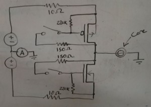
Crappy whiteboard drawing of my core test circuit.

Crappy whiteboard drawing of my core test circuit.

Above is the circuit I ended up using.  It employs a set of big TO-220 MOSFETs, one P-channel and one N-channel (I used SUP75P03 and IRFB4110, but you could use practically any other parts on hand).  I used some more 150 ohm resistors (because they were already out on my bench) in series with a couple of small tactile switches  as triggers, and put in some larger resistors from gate to source of each MOSFET to make sure they shut off when I open the switch.  You could probably use any resistors within a decade of these values and it’d still work.

The circuit is driven by two bench supplies.  In my case, this is in the form of one dual-supply which has voltage tracking, a handy feature which I originally used but which I eventually disabled for reasons I’ll get into later.  There is a 10 ohm, 10 watt ceramic resistor in series with each supply.  This is important, because you may be playing with quite significant currents, and it is all too easy to accidentally push both buttons at once and short out your supplies across the MOSFETs.  This is also why i used TO-220 transistors – they will usually happily take hundreds of milliamps without any heatsinking.  By the time I was done testing, both transistors and both resistors were fairly warm to the touch.  Finally, there is an ammeter in series with the ground line, played by a handheld multimeter.

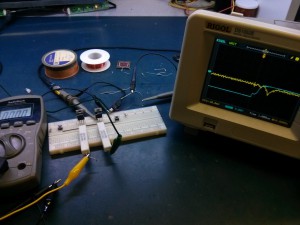
The test setup.

The test setup.

I initially set the bench supplies to about 10 or 12 volts and held one button, then adjusted the current limit to about 800mA, a little bit shy of the experimentally determined fusing current of the 36AWG core threading wire I used.  I then held the other button and did the same.  Alternating button presses, I set the scope to trigger at 20mV and a timebase of 1us/div.  And, success!  The scope showed clear pulses the first time either button was pressed, indicating a change to the magnetization of the core.  Then subsequent presses of the same button produced no such pulses, and only a press of the opposite button produced a pulse as the magnetization was again flipped.

I then attempted to find the minimum required current for changing data on the core, but I got some troubling results.  The core seemed to work down to a few tens of milliamps sometimes, and a couple of hundred milliamps at others.  I soon found – and this is so important a point that it inspired me to write this post – that you cannot use a current-limited supply to do this test.  Any capacitance at the output of the supply can cause a brief but large current spike which can unpredictably change the state of your core.  Instead, use a voltage-limited supply and rely on the series resistors to limit the current through the transistors.  You may also find that this simple circuit may not exhibit equal current output in “push” and “pull” operation.  This is why I eventually stopped using the tracking feature of my power supply and ended up setting the two supplies manually at each step.
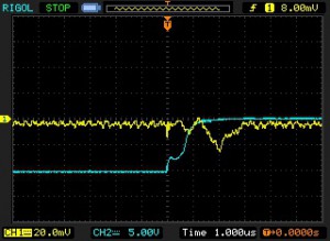
Scope capture of the signature of a changing magnetic field.  With different component values and core material, your plot may vary.

Scope capture of the signature of a changing magnetic field. With different component values and core material, your plot may vary.

Ultimately, through some trial and error, I found the required magnetizing current for my cores to be between 500 and 600 milliamps.  This was a little bit disappointing, because I expected a much lower current that I could drive with small, cheap logic transistors.  But I suppose it’s better to find out now than later.  So now, on to the array driver design… but that’s a post for another day!
Weekend Project: Macbook Pro Camera Investigation

A while back, I wrote an article on the camera in the Apple Macbook Pro A1398 lid assembly.  In that article, I published the pinout of the FaceTime camera in the lid, and demonstrated how it could be wired directly to USB and function as a generic USB webcam – but not a very cheap one, since the panel assemblies are still pretty expensive.

Well, it turns out that you can buy the bare camera module for a very reasonable $5 at everybody’s favorite auction site.  A visitor to this site wanted to use these cameras in a standalone application and offered to send me one to play with, in return for a little bit of investigative work.  Sounds like fun, let’s take a look.

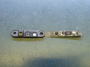
Macbook A1398 camera module, first front...

Macbook A1398 camera module, first front…

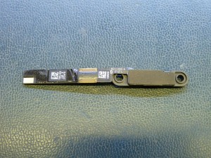
...then back.

…then back.

As a recap from last time, note that this module contains not only the camera but also the laptop’s ambient light sensor (seen at left on the front view).  There is a little foam ring around the ALS to prevent errant readings caused by the LCD backlight or the camera activity light.  Next to the right is the camera lens, and the white circle is the activity light.  The camera sensor and the ALS are on a little flex PCB which is soldered to the rigid board containing the rest of the circuitry.  Many of Apple’s other assemblies are made as a single rigid-flex assembly, but the two cameras I’ve investigated have both had separate control and sensor sub-boards.  I wonder if the camera assemblies would otherwise be damaged in reflow.

The top of the control board houses a VIMICRO VC0358SMMB.  We can assume that this is similar to the VIMICRO VC0358PQNB, for which there is a public data brief (PDF), but this part is in a wafer-level BGA package instead of LQFP.  The suggested SPI memory is probably present as the 6-pin device to the lower right, and presumably contains the USB descriptors identifying this part as a FaceTime camera.  The other WLCSP to the left looks suspiciously like some sort of voltage regulator, though I didn’t bother to measure the nearby capacitor voltages to verify that.  Note that although the VC0358 has microphone input capability, this board does not appear to contain a microphone.

The input connector is on the righthand side of the board as seen in the front view.  The connector is a 6-pin, 0.4mm-pitch FFC receiver.  I probed around the board and determined the pinout of the connector to be the same as it is on the motherboard side of the harness (pin 1 is marked with an arrow):

Pin Name Description
1 GND USB/ALS Ground
2 D+ USB Data Positive
3 D- USB Data Negative
4 +5V USB/ALS Voltage In (+5V)
5 ALS_SCL Ambient Light Sensor I2C Clock
6 ALS_SDA Ambient Light Sensor I2C Data

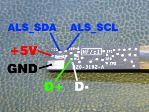
This is all well and good, but soldering to the 0.4mm connector is an absolute nightmare.  It’s not something the average person is going to want to attempt.  We could buy a little FFC jumper to plug in, but if we only paid $5 for the camera, having to buy more parts would negate that cheapness.  Thankfully, if we remove the sticker from the rear of the module, the manufacturer has left us plenty of testpoints.  I mapped the ones that connect to the connector pins, and came up with the following pinout:

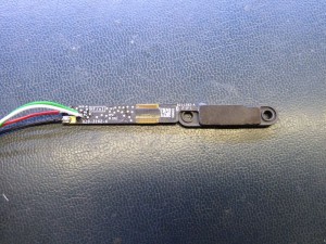
Testpoints on the rear of the camera module

Testpoints on the rear of the camera module.

Using this scheme, I soldered on an old cut-off USB cable:

Camera wired as per the testpoint map above.

Camera wired as per the testpoint map above.  The ALS pins have not been connected.

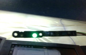
And what do you know, as soon as it was plugged in the camera was recognized the same way it was in the previous post – as a USB Composite device containing two FaceTime HD Camera devices.  Again, as last time, one of the two devices has no available driver, but the camera works just fine with only one of its sub-devices installed:

The camera takes a selfie.  Note that it's blurry mostly because I had to hold it and take a screenshot at the same time.

The camera takes a selfie. It’s a bit blurry, possibly because it can’t properly focus at this range.  I didn’t notice that when I was taking the photo, oops.

So there you go.  If you need a cheap and small USB camera for something, these are pretty easy to hack onto.  Hopefully this is useful to somebody!

Weekend Project: A Tiny Core Memory Array

Remember magnetic core memory?  Maybe you don’t, if you weren’t around in the ’50s or ’60s (or aren’t a tech junkie like me).  But it was one of the key developments during the evolution of the modern computer.  At a time when large scale integration on silicon was just beginning and massive silicon memories were infeasible, core memory fulfilled a critical need for larger, faster memories for some of the early big-iron mainframes.

Core memory is interesting because it’s one of the simpler memory constructs to understand, even today.  The basis of the system is a humble ferrite ring (a “core”).  The core material is formulated to exhibit high magnetic remanence – that is, it retains a magnetic field very well.  By utilizing Ampère’s law and passing a pulse of current through a wire threaded through the center of the core, a persistent magnetic field can be induced.  Applying Faraday’s Law, it is then possible to “read out” the state of the core – if the core already has had a field induced within it, then passing another current pulse has no effect; otherwise, a slight voltage pulse is developed across any wires passing through it,, which can be measured.

Expanding the scope a bit, it is possible to write to and read from a large quantity of cores if they are arranged on a two-dimensional grid.  As a result of the particular magnetic properties of the cores, they only change state when a sufficiently large current is passed through them.  This current can be split to any arbitrary number of wires; as long as the sum of the currents is above the minimum for the material, the field is induced.  If we pass half the necessary current through one row of a two-dimensional array of cores, and half the necessary current through one column of the same array, we can affect only one chosen core in the array.  An additional wire passing through all cores is typically used to detect the state of the chosen core.

I have an ambitious design in mind which will get a more detailed post later, but suffice it to say for now that I’m planning a combination art and engineering project which needs a bank of memory.  I could go the simple route and put a simple DIP SRAM in, but that’s no fun to look at.  But I bought a little can of 50,000 memory cores a few years ago, and that seems like it might be a little more fun.  That’s enough for a 4KB array, which ought to be enough for what I’m planning.  But before I spend several weeks building a 32,000 core array, it’s important to understand how the assembly will work.  To that end, I’ve planned a few baby-steps to build up to the real deal.

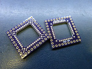
I’ve designed a simple PCB with a large route-out in the center and an array of holes around the outside.  The board is designed as a carrier for a small 8×8 array of cores and their associated wiring.  Because my application calls for byte-addressable memory, the eventual plan is to stack eight such boards to support parallel access of an entire byte, but at this point testing will begin with a single 64-bit array.

There's not much to it, really.

The corner pads are isolated by 0402 0-ohm jumpers for flexibility in stacking and addressing boards.

A core memory build is more like sewing than it is electrical assembly.  Very thin thread-like wire is woven through the cores, and the end product resembles cloth.  At the height of core memory usage there were many factories of very skilled workers who wove these memories day in and day out.  In the process of building my tiny memory, I quickly found that there are assembly methods that work very well, but there are also methods that end up in immediate frustration.  You quickly get into a groove, so while the first rows take a while, by the end the focus sets in and hours can pass in an instant as the board comes together.

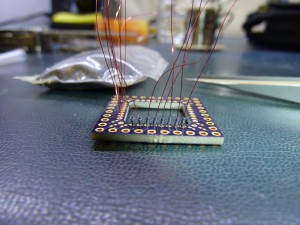
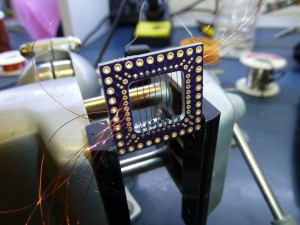
Speaking of first rows, let’s begin!  First, we solder some stubs of 36AWG enamel wire to the board along two adjacent edges, then thread eight teeny-tiny cores onto each of the eight wires on one side of the board:

CoreArray_CoresInstalledNow the wires are threaded through the pads on the other side of the board and pulled taut, then soldered into place, thereby trapping the cores:

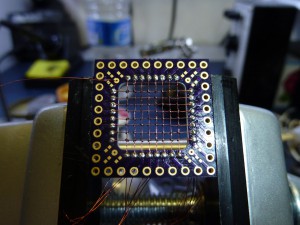
CoreArray_XWiresTautBefore we continue, an explanation is necessary.  There are a number of different ways to orient the cores.  They can all be mounted parallel to each other, they can alternate by rows, they can alternate at every part.  I chose to alternate at every part – this can reduce magnetic coupling between adjacent cores, and can enable the use of simpler read/write hardware.  It also looks pretty neat.  So after a while, the array looks like this:

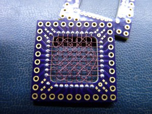
CoreArray_XYWiresInstalledNow that the main array wires are all installed, the sense wire must be threaded through all the cores.  Each core must have the sense wire passed through it exactly once.  With the cores in this arrangement, this is simplest to accomplish by passing the wires through the cores diagonally, first in one direction, then the other.  That leaves us with an end product that looks something like this:

CoreArray_FinishedAnd that’s the current state of things.  The corner jumpers and connectors still need to be installed, but that will come when the interface hardware has been developed.  There’s still plenty of work to do, so watch for followup post(s) later on.

Schematics and Gerbers for this board will be posted… as soon as I get around to it. below:

PCB10024 REV A GERBERS (zip, 6KB)
SCH10024 REV A (pdf, 18KB)

Please note:  The board has a large cut-out in the center.  The first time I ordered these, OSH Park correctly routed to the edge of the definition line (as shown in the above photos).  The second time, they routed on the center of the definition line, cutting into the ring of pads.  The resulting boards are functional, just not as pretty.  Watch out for that.

A New High-Resolution Panel – Sharp LQ156D1JX01, Part 1

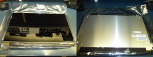
I’m a huge sucker when it comes to playing with shiny new tech, and straight from the shiny tech factory I’ve gotten ahold of a new toy which in terms of raw number of pixels puts the previous panels I’ve been working with to shame.  Say hello to the Sharp LQ156D1JX01!

It's pretty glossy.

It’s pretty glossy.  Look, a reflection of some of my test equipment!

The LQ156D1JX01 is a new inductee to the ultra-high-DPI panel club, whose members have lately found their way into many high-end gaming laptops and ultrabooks.  This particular panel is a pull from a Toshiba Satellite P50T.  The panel measures a whopping 3840×2160 pixels (that’s 4K, or 8.29 megapixels!) in a mere 15.6 inch size.  Now, that doesn’t quite compare to the current generation of cell phones with 5-inch 4K screens, but at something like 282PPI it’s nothing to scoff at either.  This pushes far above the 220PPI of the Macbook Pro Retina panel that we’ve played with before, and puts it somewhere between the 264PPI of the iPad 3 Retina panel and the 324PPI of the iPad Mini 2 Retina.  Like the Macbook and the iPad, the LQ156D1JX01 runs on 4-lane Embedded DisplayPort.  Where it differs a bit is that this panel is reportedly addressed as two 1920×2160 half-displays over DisplayPort 1.2’s Multi-Stream Transport.  This may have been done to simplify timing requirements for such a massive display.

I don’t happen to have a proper connector on hand for this panel so I haven’t fired it up yet, but like any good engineer, before even bothering to plug in my new toy I went ahead and tore it apart.  This was actually a necessary step, because there is currently no publicly-available datasheet for this panel, so we need to figure out the pinout of the connector in order to make it do anything anyway.

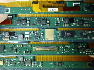
LQ156D1JX01 control PCB top side collage

LQ156D1JX01 control PCB top side collage

Before delving into the pinout, we can find out several things about this panel by looking at the design of the control board.  The main connector is made by Dai-ichi Seiko I-PEX and appears to be a 40-position CABLINE-CA series part, possibly 20525-040E-02 (pdf link).  The panel is driven by a Novatek NT71394MBG.  This part does not seem to have any publicly available information, but we’ll assume it’s a timing controller ASIC.  There is a TI power management IC that appears to generate all the necessary panel voltages; I think it’s a TPS65642A (pdf link).  There are also two chips marked 89=1D, these are Richtek RT8532 boost LED drivers (pdf link).  The design of the backlight flex implies that each of these ICs drives four LED channels, despite being capable of six.

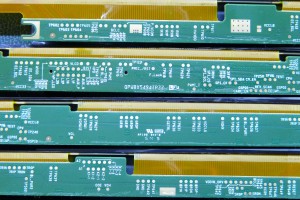
LQ156D1JX01 control PCB bottom side collage

LQ156D1JX01 control PCB bottom side collage

Now that we have some idea of what’s going on in the panel, on to the pinout.  Thanks to Sharp, this task is simple, because all of the pins are connected to convenient labeled testpoints on the bottom of the board.  I haven’t tested the panel yet so I don’t know if this is 100% accurate, but as far as I can tell at this point, the pinout for the LQ156D1JX01 is as follows:

Pin Name Description
1 PMIC_/RST Power Management Reset, Active Low
2 GND Ground (Shield)
3 L3N Embedded DisplayPort Lane 3 Negative
4 L3P Embedded DisplayPort Lane 3 Positive
5 GND Ground (Shield)
6 L2N Embedded DisplayPort Lane 2 Negative
7 L2P Embedded DisplayPort Lane 2 Positive
8 GND Ground (Shield)
9 L1N Embedded DisplayPort Lane 1 Negative
10 L1P Embedded DisplayPort Lane 1 Positive
11 GND Ground (Shield)
12 L0N Embedded DisplayPort Lane 0 Negative
13 L0P Embedded DisplayPort Lane 0 Positive
14 GND Ground (Shield)
15 AUX_P Embedded DisplayPort Aux Channel Positive
16 AUX_N Embedded DisplayPort Aux Channel Negative
17 GND Ground (Shield)
18 VLCD 3.3V LCD Power
19 VLCD 3.3V LCD Power
20 VLCD 3.3V LCD Power
21 VLCD 3.3V LCD Power
22 BIST Built In Self Test
23 GND Ground (LCD Power)
24 GND Ground (LCD Power)
25 GND Ground (LCD Power)
26 GND Ground (LCD Power)
27 HPD Embedded DisplayPort Hot Plug Detect
28 GND Ground (Backlight)
29 GND Ground (Backlight)
30 GND Ground (Backlight)
31 GND Ground (Backlight)
32 BL_EN Backlight Enable
33 PWMI Backlight PWM
34 EE_SCL EEPROM Clock (EDID?)
35 EE_SDA EEPROM Data (EDID?)
36 BL_PWR1 Backlight Power
37 BL_PWR1 Backlight Power
38 BL_PWR1 Backlight Power
39 BL_PWR1 Backlight Power
40 WP_LCD Write Protect?

I have not marked the backlight voltage in the table, because I am not certain what the design voltage range is.  RT8532 has an operating range from about 5V to 24V, but it is not currently known what the components in the display are actually rated for.  My guess is it’s probably safe up to at least 12V, but try at your own risk.

It’s interesting to see EEPROM pins brought out.  I suspect these are for the EDID EEPROM, maybe for factory programming of the device. Or maybe it’s something completely different.  Again, without having fired up the panel, this is all speculation.  There is an explicit “EE_WP” testpoint which is not the same as the “WP_LCD” that is brought out; I don’t have any good idea for what the latter may be used for.

So that’s about it.  The next step is to wire up a connector and get the panel running, but that won’t happen today.  Stay tuned for a followup post.

Miscellaneous updates, 2015-01-31

Well, this is embarassing.  So much for my minimum-one-post-per-month goal.  Between working on the new house and real salaried work and some contract work on the side, I haven’t had a lot of time to post anything useful here lately.  Believe me, I’m just as disappointed as you are.  But never fear, I’ve just sent a new batch of boards off to be manufactured.  These boards are related to a previously-undocumented new project I’m working on, so there’ll be some new and interesting stuff to post in just a few short weeks.  Hopefully.

Beyond that, I’ve got some sort of left-field development I’m about to start on – a departure from the display stuff that’s gotten kind of repetitive for me.  As usual, stay tuned.

Miscellaneous updates, 2014-09-07

Good day all,

Just a quick note to reassure you all that I’m still around.  As alluded to in the previous post, in July we bought a new house, which happily has plenty of space just waiting to be adapted to a well-equipped electronics lab.  Before I can get back to hardware design, I’ve got a lot of work to do – all my test equipment and projects-in-progress are still spread amongst dozens of storage bins.  The lab, a previously unfinished area of the house, needs lighting installed and electrical and data wiring run in addition to furniture and storage needs.  Getting the lab up and running in full capacity is my immediate concern, and I appreciate everyone’s patience during this process.  Updates on the projects on this site to follow… someday.

Miscellaneous updates, 2014-06-24

Hello all!  I apologize for the long time without updates.  Paying work has kept me busy enough that I haven’t had much time to work on this stuff for the past couple months.  I don’t have any new information to give, actually, just wanted to say that no, the site is not dead, I’m still here, just busy.

What I do need to say is that I will be moving sometime in mid to late July, and with me will come the server that this site runs on.  This means there may be up to a week of downtime while service is transferred to the new house and everything is set up.  Be patient, I’ll come back, I promise!

[EDIT 7/9/14] Oops… the move hasn’t happened yet, but the site’s been down for a while (days? weeks? I’m not sure) due to an IP reassignment that didn’t get propagated to the DNS.  Sorry about that.

[EDIT 7/17/14] Server move is complete.  Hooray!  Now, to move my test equipment so I can continue working on these projects…

Weekend Reverse-Engineer: Passive DisplayPort Adapter

Displayport adapter dongles are ubiquitous, now that DisplayPort is becoming more and more prevalent in desktop video cards.  I probably have at least a half-dozen of them, connected to machines or stuck in junk drawers.  You plug them in, and they work.  Simple.

You are probably aware that there are two different adapter families, passive and active.  The former is cheaper but is limited in the number of adapter that can be used on a single GPU; the latter is more expensive but has no such limitation.  So there must be something different going on inside.  But does “passive” mean here what it means in traditional electronics, that the conversion requires no transistors or ICs or other “active” components?  (For a formal definition of passive vs active, see this Wikipedia article)

Before we answer that question, let’s back up a bit.  Backward compatibility is an important factor in the success or failure of many new technologies.  In the case of DisplayPort, if it was meant to displace DVI and HDMI on the desktop platform as its creators intended, it would need to support legacy equipment.  The problem was that DisplayPort is a very different platform than DVI.  Whereas moving from DVI to HDMI is fairly painless since both schemes use the same signaling standard, DisplayPort more closely resembles PCI Express than DVI.  So “something” has to go in the middle, to convert from one standard to the other.  And in the most basic form, this is what an active adapter does – it takes in native DisplayPort signals, decodes them, and converts them to DVI/etc.  But that signal processing is complex, and adds cost to the system, which impedes adoption for some markets.  For more cost-conscious applications, an alternate scheme was created – Dual-Mode DisplayPort.

In Dual-Mode DisplayPort, or DP++, the DisplayPort source (typically, a GPU) can be requested to output raw TMDS data, instead of normal DisplayPort data packets.  The data that comes out of the GPU looks electrically like DisplayPort, but the data is in DVI format.  A DVI monitor can’t directly use the electrical signaling format of DisplayPort, so a low-cost level shifter is required in the middle.  You may now realize that we’ve answered our original question – in fact, a passive DisplayPort to DVI adapter does require active circuitry.  In this case, Passive refers to the fact that the video data is not mangled in any way, whereas active adapters decode and then re-transmit the video stream.  DP++ enables very low-cost adapters because the logic is simple, with all the heavy lifting being integrated (cheaply) into the GPU.

So enough talk.  Now that we know what’s going on, let’s take a look at a passive DisplayPort adapter:

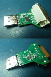
A passive DisplayPort to DVI adapter, with its casing and potting removed.  I've removed and re-installed components for testing prior to taking this photo.

A passive DisplayPort to DVI adapter, with its casing and potting removed. I’ve removed and re-installed some components for testing prior to taking this photo.

As you can see, there is one large IC on top, which predictably handles most of the functionality of the adapter – this is the previously-mentioned DisplayPort-to-TMDS level shifter.  These parts are available from a number of manufacturers – there are options from TI, Maxim, NXP, and many others.  This unit happens to use a Pericom PI3VDP411LS.  The competition and the high volumes of these parts have had a favorable effect on the price; the ‘411 can be had from several distributors for less than $1.50 in qty 1.

The rest of the components are primarily support components for the main level shifter IC.  There is a 10A45 charge pump to generate 5V for the attached monitor (per DVI spec) from the 3.3V available from the DisplayPort, and there is a 2N3904 transistor to switch the level shifter on when a signal is received on the HPD pin.  The rest are passives, mostly resistors and capacitors and one or two ferrite beads or little inductors for noise suppression.  I’ve transcribed the design into a schematic, which you can download here:

It’s missing a few values, mainly because I was too lazy to pull all the components off the board to measure them and I couldn’t satisfactorily do it in-circuit.  Most of the unmarked capacitors are going to be 0.1uF or 0.01uF decoupling capacitors for the level shifter.

I don’t have an active converter to tear down as well to show the differences.  What I can say is that the internals will look similar, but they will operate very differently.  As noted above, the complexity involved in decoding and re-transmitting the signals in an active adapter is very different than the simple level shift operation of the passive adapter.  Regardless, it will probably be implemented as a single IC, albeit possibly a larger one with more support components.

I suppose that’s enough rambling on this topic.  Hopefully this all makes sense!

New project: Slightly-Less-Simple Retina LCD Adapter

As many have noticed, I’ve stopped offering my Simple iPad LCD Adapter for sale.  The reason I’ve given is that I am working on an improved version of the board.  Well, as of today I’ve gotten far enough on the design that I’d like to share it.

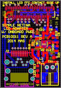
The new Simple Retina LCD Adapter, work-in-progress.

The new Simple Retina LCD Adapter, work-in-progress.

The most drastic change for this design is the integration of buck and boost power supplies to drive the panel and backlight respectively.  I was not happy with telling people they’d need to provide their own regulated power – the panel isn’t THAT sensitive to voltage wobble, but it can be a problem with particularly long power leads, despite the large hold-up capacitor.  Now the board should be able to take between 5 and 18 volts and spit out well-regulated rails.

Several other things have changed as well.  I’ve changed the full-size DisplayPort connector to a miniDP connector, because for as small as the board is, the full-size connector was a waste of space.  I’ve added a proper connector for power – while handing out boards with bare wires soldered on was functionally workable, it’s not exactly as clean a solution as I prefer.  There is no longer a diode OR between external and DisplayPort power, because cables that carry DP_PWR are so uncommon that it is unnecessary.  And there’s a fuse, to limit catastrophic failure in the event of a solder bridge or improper installation.

Now, the added components will increase BOM cost – I’m not sure by how much, but I know it will.  However, I have designed in jumpers that will allow users who still want to feed in their own 3.3V and who don’t need a backlight supply to use this board in the same way as the old one.  Hopefully this will make the design more accessible to people who want a more compact, all in one design without alienating those who like it how it was.

The design is a day or two from completion.  As per typical, I’ll be building a board up and debugging it before I release the design documents, so that I don’t release something that won’t work.  So keep an eye out in the coming weeks.