Now that the main board has been put on order, my focus can shift to the ancillary parts of the project. In particular, it is time to consider the human-interaction part of this build. I think it is important to be able to control the brightness, as well as overall system power, of the panel. Some designs handle brightness via the USB HID monitor class, and I may well go this way eventually, but for the short term I would rather have simple up/down/off button control, so I can have immediate gratification before I spend the time to write the HID software.
Most monitors have some controls in the lower righthand corner – power, up/down, menu, etc – as well as a status LED. As I will not be inserting video data and thus will not have an OSD, some of these buttons are not important. But I think the lower-righthand corner is natural for monitor controls, so my plans call for a simple board adhered to the back of the panel at this point, with basic controls and a status indicator LED. This will connect to J8 on the main board, which has been wired for this purpose (three active-low button inputs pulled high, and three resistor-limited PWM outputs). I have chosen to use a RGB LED because I have not yet decided on indicator colors. Perhaps white would have been ideal for this application as it is an Apple panel, but I couldn’t find a white + orange (for standby) LED. I chose a 0604-size 6-pin LED (Rohm SMLP36RGB1W3), so I could fit discrete white and orange 0402 LEDs if I wanted to change to that.
For buttons, I was really torn. On one hand, it would have been nice to have the whole board hidden from view, and use right-angle buttons just exposed beyond the edge. I couldn’t think of a good way to show the LED though. I thought about capacitive touch buttons, which would be neat and fit with the Apple theme of the unit, and I actually wired the button inputs to capacitive touch inputs just in case, but I didn’t want to bother with the software and debugging right off the bat. So I went with regular SMD microminiature tactile switches (C&K KMR421G LFS). These are seriously, seriously small buttons. They should end up no taller than the panel is thick (and if you have a panel, you know how crazy thin it is), and allow my exposed board area to shrink to 0.14″. So enough talking about it, let’s have a look, eh?
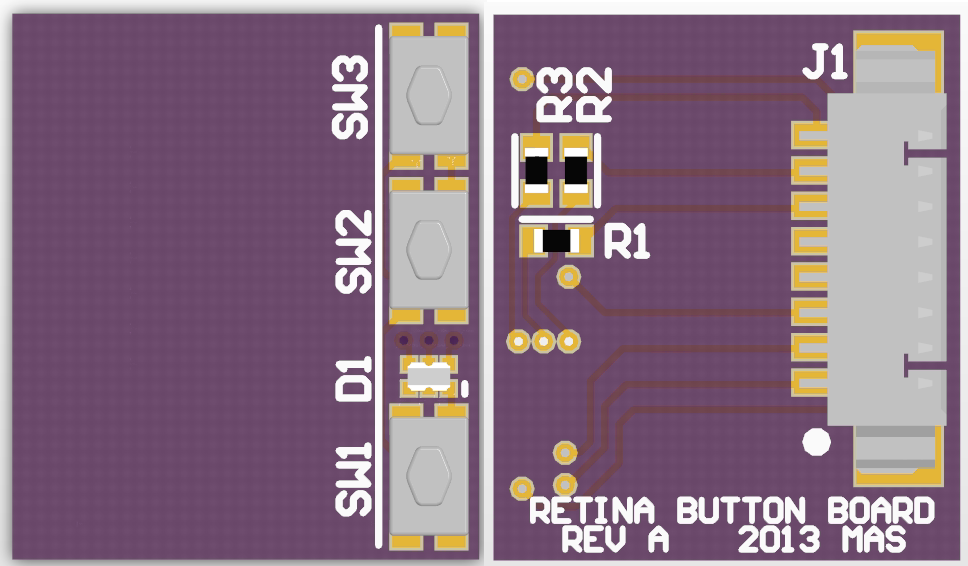
First go at the iPad LCD controller interface board. It’s smaller than it looks.
You’ll notice a couple of things about the design. First, note that there are no traces or copper features on the left section of the top of the board. I plan to adhere this board directly to the back of the panel, so I made sure there was no copper (even under soldermask) that could be rubbed through and short on the back of the panel. Mind you, this circuit was designed with short circuits in mind, and nothing will be damaged, but if it shorts it won’t work right and I’ll be peeved. I think I will use contact cement to adhere this board rather than the foam tape of the other one, as it is designed for flat contact and has no components or pins like the other board does.
You’ll also note that the bottom side traces extend straight for a quarter inch from where they are routed to the connector. I actually made this board larger than it had to be, because I didn’t think I could get good adhesion in only a quarter-inch of mating surface. I kept the traces straight in this area so I could easily make the board wider or narrower as needed. The total board dimensions are now 0.65 by 0.76 inches, driven in X by adhesion area and in Y by the components themselves. This board is 2-layer and should be very inexpensive (at $5 per square inch, my math works out to $2.47 per 3 – I wonder if OSH Park has a minimum order?), so I plan to order it and just see how it works without putting too much more thought into it.
I spent a little bit of time deciding whether this will end up too small, and in doing so drew up a quick model of the boards in place on the LCD. Decide for yourself if I’m crazy.
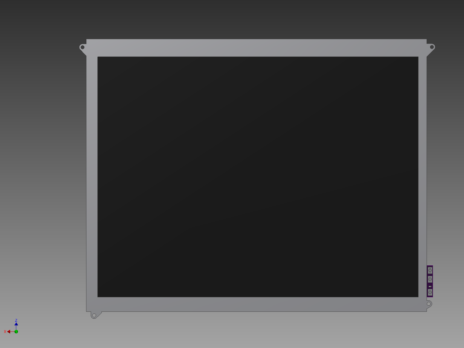
Assembly concept 1, top
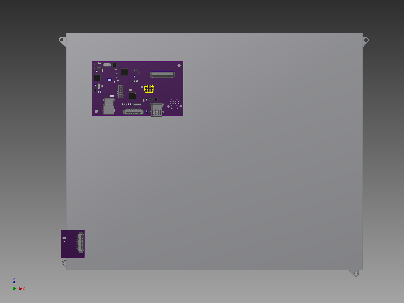
Assembly concept 1, bottom
I don’t have the FFC modeled in yet, but assume it would naturally plug into the connector in its current position. I also haven’t bothered to model any structural components, which I also haven’t mentioned yet. In lieu of a full case, I think I’ll do a minimal support structure out of 1/8″ aluminum bar stock – a strip down each side to catch the mount pads, one across the back and a hinge with a foot so it sits upright on a desk. I’ll talk more on that when I get that far.
Documents for the button board are available for download:
In the process of generating these prints I did a little more measurement and I think these will be way, way too small. But what the hell, they’re cheap, so I ordered them anyway. You may want to wait for Rev B.
Hi
I know you’ve been asked this before, but is it possible to order a set of 3 of either the larger or simple board. I would msot probobly prefer the Less Simple design, just for the simplicity and dull wittedness in case i ‘derp’ up.
I couldn’t see the new gerbers or layers for the new simple board with a wide input range,. Also would it be possible to set it so the input range sets the brightness, ie have a external driver with dial to set the voltage?
I know there is some errors in the firmware atm but i do not mind having to change it over at a later date if need be, and dont mind if the button board is changed as it is such a simple pcb, if you still use the same connector.
I am wanting to start up a project similar to yours in time (i am slowly learning eagle), just to spend my spare time on,i already have 2 of the 3 ipad3 displays coming to me, and also the triple monitor arm is coming along nicely to fit them.
I hope your projects and real life is going well, Hope to speak soon.
Brendan Holland
Hi.
Do you have these board to sell?, do they support hdmi input?…
Thanks?
Hi, Mike.
Sorry 4 my bad English, I am from Russia, & this text I wrote by Google Translator.
Actually, I wanna buy 2 pieces Hacking the iPad Kit ( only kit, without working) & 2 button board for this. How much? Can I pay to you with PayPal?
Thank you, friend.
I am unfortunately not currently selling boards, sorry!