Much has happened since the last update. I have received a panel, as well as the balance of the components that I ordered. The panel has a half-inch scratch on the front, so hopefully it is still functional.
The design has been steadily progressing. The architecture of the board is now a bit more complex – a Freescale Kinetis-L2 (ARM Cortex-M0+) processor is onboard, primarily because it was cheaper than the competing TI MSP430 that I had planned on using, go figure. To accompany this, a Mini-USB header has been added. This will not power the system as per other folks’ designs because I refuse to violate the USB spec (and my motherboard) that badly, but it will allow for connectivity to the host in order to (hopefully) enable control of the panel from keyboard hotkeys. A Linear Technology LT3502 switching regulator has been added to provide 3.3V for the panel and the processor, and a Skyworks AAT4618 high-side switch was put in place to allow power to the panel to be disabled when the system is inactive for greater power efficiency. The board should operate from something like 8 to 40V DC, for whatever power adapter you happen to have around that fits.
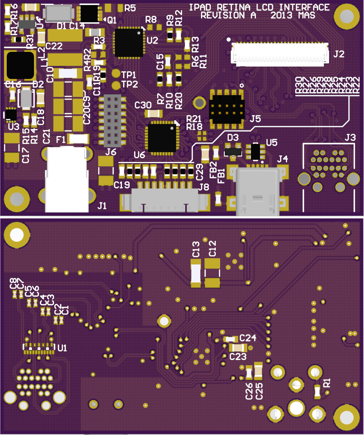
First run of the full-function interface board, revision A. I was too lazy to add some of the 3D models. For a sense of scale, the corner pads are sized for a 2-56 screw.
So there it is. The board is now fully routed and has been sent out for manufacture. Naturally this means I’ve started noticing errors in it, but I’ve not found anything that means it altogether won’t work. Getting matched trace lengths on the mDP lines took a couple hours, and was probably the one most time consuming part of the design, but now all 8 lines are matched to within 10 mils. This is probably excessively close, but what the hell – as long as we’re doing it, may as well do it right. The final dimensions of the board ended up at 2.525 by 1.5 inches – quite a bit smaller than I originally planned on. And it is dense. We’ll see how well everything works.
(2013-05-07) I will not be releasing documents for this board for a while as I have noted a serious flaw in the processor section. I will use these for debugging the power system then respin the board when I am satisfied.
<< Previous post in this series … Next post in this series >>
Really nice work, I envy your layout skills (and speed!).
Is J8 the matching connector for the touchscreen or general purpose? And why did you choose Mini-USB over Micro (which seems to be all the rage now)?
I have found that Mini-USB doesn’t use and more actual space the Micro, and the connectors don’t break nearly as often.
As Joe pointed out, ruggedness is the reason. Micro just always seems to require more mate and unmate force than I’m comfortable giving to such a thin connector. Also nearly all of my surplus cable stock is either full size B or Mini, hardly any Micro (I got my first Micro device only a couple of months ago).
J8 is for another board I’ll be going over in another post. It adds buttons and an LED to the bottom-right corner of the panel. J6 however is a generic expansion port that breaks out all of the unused pins from the processor, and that may well get some use as a touchscreen interface.
In hindsight, I am just realizing at this instant, I could have extended this board past the edge of the panel and just put the LEDs and buttons on it, no additional board needed. Oh well, too late now. Plus I think buttons at the lower-right is more natural anyway.
Actually, the Micro USB connector was designed to be more durable than the Mini (10,000 vs. 5,000 insertion cycles). However they seem to get ripped off the board more often than the Mini.
Hmm. You’re absolutely right, the PCB receptacles for Micro are rated for more mate/unmate cycles than Mini. I don’t know that that’s critical in this application (how many times do you have to move a monitor before you plug in the cables 5000 times?), but good to keep in mind. Plus the two have very similar footprints so it’s a 5-minute swap if need be. Will keep that in mind for future revisions.
Mike,
I realize your reluctance to release information on your incomplete design. But I was wondering If you could possibly release the schematics and/or parts list for this board?
additionally has any more progress on this more advanced board been made?
Well, nobody’s asked about this one in a while! Actually the changes have been made, I just haven’t had the time to order the board and update the site. If you would like the schematics I can probably send them to you via email. I just don’t really want people ordering this board willy-nilly, and then being angry when it doesn’t work – I released the Simple board like that, and I never heard anything but I’m sure some people were none too pleased.
That would actually be great, thank you !
did you ever order this board (the non-revised version) specifically/ if so how did it work?
also how was the usb set up in relation to the ARM Cortex-M0+, I understand the intent to use keyboard hotkeys, but how did you plan on flashing the chip?
I did order the “original” version, yes. At the time I did not have the software written for the processor yet, so I bypassed some of the features – the panel power switch was removed and bridged; the enable and PWM lines for the backlight driver were pulled up with a resistor for “on, 100% duty”. The major issue with the first rev was of course that the DisplayPort lines were reversed, so some cuts and jumps were made with magnet wire. After all that was done, though, the board worked fine – that is, the backlight driver ran as expected, all the power supplies worked, and the panel displayed a picture. (The reversed DisplayPort lines and the omitted USB crystal were the reasons I didn’t release documents for this board)
The Cortex-M0+ has a hardware USB interface, to which the USB is connected. The normal intent, as you have noted, is to allow the PC to send commands to it via a HID Monitor interface. But its dual use was also to allow it to function as a firmware update port. The problem with this plan is that I am new to the platform, and I don’t yet have enough skill to write a DFU utility for it. So for now the device is programmed via a standard 10-pin Cortex Debug Header – actually I use a Freescale FRDM-KL25Z Freedom development board as an offboard programmer, since its onboard target device is the 80-pin version of the same processor I used.
Hi Mike,
Really nice and useful design, are you using LT3754 BL driver? I’m a student, would you please send me the part of schematics about LT3754 only? Only want to learn some details about that. Thanks!
I can probably do that. If you don’t get an email from me within the next few days send me another message, I’m awfully forgetful sometimes!
Hi,mike I would like to have one of your schematics on this project ,if you could send me one via email,that’s very nice ,thanks very much. Wish your email.
Hats off to you Mike for your achievements and dedication to these projects. I see more of these boards appearing online, however there is none that can bridge hdmi to eDP. Is this a possibility for you in the future. I have done some searching around for various chips that could do this but have not found anything suitable. Although I have seen some that can convert HDMI to MIPI and MIPI to eDP. Is this a possible solution? Thanks.
We can also do HDMI to parallel RGB, RGB to DisplayPort, the latter via ITE IT6251. That should be simpler than having to deal with MIPI DSI, and is even fairly simple to obtain. I have a plan to design a board with that part… now all I need is the free time to do so 🙁