In the comments for Part 2 of the main series, the desire for a comparatively simple interface board was noted. From the comments in the original thread and from the Hackaday writeup, a number of people have expressed interest in using the panel as a projector, ala the now defunct LumenLab plans.
Compared to my plans for the full-fledged panel interface, this application is a whole lot simpler. A large external light source serves as the backlight, so no backlight driver is necessary. With no backlight, there is no need for generation of voltage rails onboard as the whole unit can be run off a 3.3V input. And presumably power and brightness control can be handled externally, so no processor is needed onboard.
I had a couple hours free, so I took a swing at generating a board for the DIY projector crowd. At the suggestion of commenter Joe (and as an exercise to see whether it made the routing any simpler), I this time used a full size DisplayPort connector. This made the fanout a lot simpler than the mDP I am using on the full-function board, at the expense of some real estate. But the design remains fairly compact. It is worth noting that DisplayPort’s pin ordering is different from the iPad FFC. This means that they cannot be simply wired straight through, and must be routed between layers. The least troublesome way to do this was to place the FFC on the opposite side of the board to the DP connector – this wouldn’t be ideal for my main controller board, but works here as the tail of the LCD will be held away from the back of the panel anyway.
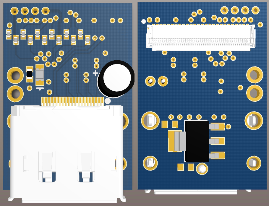
Top and bottom of a simple DP to iPad FFC adapter. This image does not show the final silkscreen.
Not much magic going on here. The data lines are straight passthrough from DP to FFC. The twelve backlight cathodes are connected in two banks of six and brought out to pads, on the off chance that this board might be used with the backlight intact. To facilitate proper backlight driving, individual 0402 resistors are placed on each of the twelve strings. Power is diode-ORed between the DisplayPort connector and pads for an external 3.3V adapter, to allow powering from either source without backfeeding to the other; 0603 bypass pads are provided in the event that the diode is not desired or required. A 5mm electrolytic capacitor is on the output of the diode to stiffen the sources during current peaks. Finally, a LED indicates the presence of power from either source. The whole unit comes in at 0.810″x1.175″, barely larger than the DP in width.
So there you have it. A design for a simple breakout. You can go ahead and grab the board documents here:
[2013-06-13 UPDATE: The Rev A documents for this board contain an incorrect pinout for the DisplayPort connector, and have been removed. The Rev B documents which fix this issue are posted in the next part of this series.]
I plan to order one set of these to test and debug in the short term, but beyond that would be more than happy to work with anyone else who might want one.
I hope we can get these into production soon I would be very interested in this design. Mike I like the design!
The next OSH Park 4-layer panel is being run on May 15 – I just missed the May 1 panel. These boards will for sure be on that order. For less than $10 per set of three, I may just go ahead and order two sets and assume they’ll work ok. I don’t have the $100,000 oscilloscope necessary to do eye diagrams on this sort of thing, so all I can do is run it and see if it works… hopefully best practices are enough to provide a sufficiently-functional board.
When I release the documents you are welcome to order a set yourself, or if it makes sense we can probably work out a bulk-buy of boards + components.
I would very much be interested in bulk buying . I may just order a set for my self at first and get a feel for them before I do though. There is a definite demand for these especially considering the price and quality of the panels.
I’m enjoying this hack!
Thanks! I’m glad people are watching this… that motivates me to hack more and post more.
I’m getting 3 produced, total cost including components comes to about $20 a board which is really reasonable.
Happy that your site is back up!
I did a hand soldered version of the eDP -> DP a month or three ago after seeing that it was possible as I saw one on Taobao, and it was just a matter of getting the pinouts from the Intel Whitepaper (as the iPad side was readily available pinoutwise).
Was about to get your pcb made as others were interested, and doing things by hand is just too much of a pain, and the site went off!
Will teach me next time to always save content on random sites I visited just in case(tm).
Keep up the good work.
Holy cow, a real comment! All I typically get is spam these days…
Yeah, sorry about the outage. I host the site on my home server, which is built from reject parts from my employer and isn’t always reliable. Sometimes it runs for months, sometimes for an hour. I went on vacation for a few days and didn’t have the ability to care for it, so naturally it went out.
I’m glad to see someone benefiting from the stuff here. Do proceed with caution though – I just received these boards back and built them up and my panel is giving me DP Link Failure issues. I currently am suspecting the panel rather than the PCB, but I can’t confirm that until I get another panel to test.
Nice work on the LCD and Touch projects. Glad to see your site back up again. Which PCB program do you use? Looking forward for continued posts.
I use Altium Designer (currently version 13.2) for my PCBs. I use it professionally at work, and it’s the only package I know. Though I have always been curious to try Eagle.
So how do we get our hands on one of these , building a diy projector , these will work perfectly , good job by the way
Thanks! DIY projectors is exactly why I built this board. Well, that, and the desire to get up and running with the panel right away before finishing the version with all the bells and whistles.
You are free to order the boards yourself using the attached Gerbers – I have ordered them through OSH Park and it processes them just fine. You are also welcome to use your choice of other board houses (Seeed, ITead, etc) – but be cautious as other board houses will use other layer stackups, which will affect the impedance of the DisplayPort pairs. I will warn you, without some proper tools assembly will not be fun. At very least you will need a good soldering iron with a very fine tip, anything below a Hakko 936 isn’t going to cut it. I think it’s hand-solderable, but I’m really not sure – I used solder paste and reflow-soldered mine with a toaster oven, which took magnitudes more setup time but I think it was ultimately easier.
If you’re looking for a finished board, that’s a little more difficult. It takes me a few hours to assemble one of these right now, since I didn’t buy stencils – I carefully apply the paste with a toothpick. This is not an economically feasible way to build boards to sell. Pololu makes stencils of this size for $25 though, so if a few people wanted one I could roll that into the distributed cost and make it work, but it’s not feasible for a single unit. Got any friends? 🙂
In any case, you may want to hold off on working with this design until at least mid-week. As I noted a few comments back, I’m having trouble getting my existing panel to work with the design. I am currently chalking it up to a bad panel and should have two more in hand by 6/13, but if it’s a flaw in the design I don’t want you wasting money. I’ll post a followup to this as soon as I have some more definitive information. I may also look for an alternate FFC for the panel connector – it is possible to insert the panel cable upside down, which will damage it.
I might have missed it in your posts, for the DP signals did you maintain 100 ohms +- 20% differential impedance to maintain signal integrity?
As close as I was reasonably able. Using the OSH Park stackup of 1 oz copper over 6.7 mil prepreg using FR408 substrate Er of 3.66, I chose minimum (6 mil) spacing and selected 7.9 mil trace width to achieve a calculated differential impedance of 101.4 ohms – it’d be closer, but I used Saturn PCB Toolkit’s built-in figure for FR408 Er of 3.8 (at 3.8 the Zdiff is 100.025 ohms). I didn’t account for connector or via impedances because I don’t have much experience calculating their effects, but I can’t imagine it’d be enough to throw things out of spec.
Rob, are you the same Rob from 43oH? If so, i’m inspired by your work. Other than that, I really look forward to more of these post, I check every day. By the time I have the cash saved for a panel or 2 and get my 9 boards back, the panel will be out of stock everywhere, lol. Great job Mike!
different Rob