Today, a post on one of my favoritest sites (Hackaday) piqued my interest. The post was titled Connect a Retina display to a regular computer. I have always been a huge fan of high-resolution displays, but they have traditionally been far outside my price range. But here, says the article, is a massively high resolution display, with simple drive characteristics, that can be had for only $55.
I bought some immediately.
The post links to the efforts of [Andrzej] and his post on the subject, http://emerythacks.blogspot.com/2013/04/connecting-ipad-retina-lcd-to-pc.html, and if he should ever happen to run across this page I sincerely thank him for his work in this area. But I am nothing if not a perfectionist, and happen to be an electrical engineer by trade with some high speed design experience, and I have been working on some very similar things at work, so it seems an excellent opportunity to improve upon the original design and make something a little cleaner.
So here’s the plan of attack. While the displays make their way to my house, I will begin the design. The display is a LG LP097QX1-SPA1, for which I have a half-Korean datasheet posted here: LP097QX1-SPA1. (Edit: A somewhat less Korean datasheet for the similar -SPC1: LP097QX1-SPC1) The datasheet outlines the pinout of the display, in the following manner:
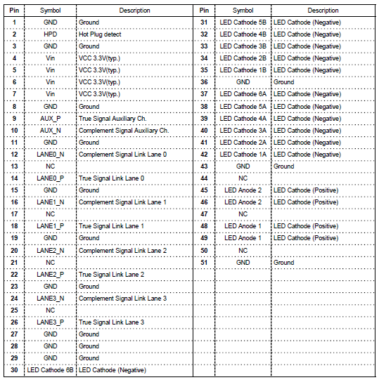
Neato! It’s just DisplayPort and power and LED strings. We can deal with this. DisplayPort means no pesky EDID EEPROMS, and no finicky LVDS data format issues. Should be a cakewalk. However it is also worth mentioning that what you see is what you get. There is no capacitive touch interface here. That is all found on the transparent glass digitizer normally attached to the front of this LCD. A lot of people in various forums seem confused on that topic. I purchased a digitizer as well, but I give no guarantees on how far I’ll get on that.
Based on [Andrzej]’s original writeup, I will be emulating his work while adhering to the following additional guidelines:
- I hate splicing wires. I have done plenty of Apple Display Connector to DVI conversions (hint: topic of a future post), and I really hate having to splice itty bitty wires. It’s also a great testament to the hardiness of DVI that the display works with such a simple fix, as the resultant signal looks horrid. I don’t have so much faith in the higher-frequency DisplayPort signals, so I will be designing the solution with a standard mDP connector onboard.
- Driving LCDs with a constant-voltage supply is not ideal. I know it works, but LEDs are constant-current devices and are either hard to drive adequately or easy to overdrive with a constant-voltage supply. I have designed a reference circuit for a six-channel LED driver for a project at work, and will attempt to adapt this to the 12 strings of this display.
- Everything worth doing is worth doing right. If it’s not worth doing right, it’s not worth doing. This is really the most important thing to remember about this and every project. I really hate half-arsing projects, so much so that many of my projects have been put on semi-permanent hold if they fail to live up to the initial elegance expected of them. This mod should provide an elegant, highly usable, production-quality end product, or I just won’t end up using it.
I believe my plans to be reasonably sound, but I do have a few nagging questions remaining, primarily concerning the backlight. In a traditional embedded system, the display controller has control over the backlight state and brightness, and wiggles the controls of the backlight driver to its whims. In a commercial DP monitor, the monitor’s display controller pulls this information from the DP data. But in this application, the DP signal data is simply passed through from input connector to panel, no post-processing included, and no additional backlight controls are presented, so presumably the backlight will be on all the time (which is undesirable). IPS displays are thankfully naturally black, but that’s no real consolation for a system being designed as elegantly as possible. I will need to investigate this issue when the panels arrive. I also need to think through backlight brightness adjustment, because again no backlight level control data is exposed.
Next step is to start blocking out the main components of the interface board. As I have nothing yet to show, I’ll leave that for the next post, so that’s it for now. Thanks for watching!