As many have noticed, I’ve stopped offering my Simple iPad LCD Adapter for sale. The reason I’ve given is that I am working on an improved version of the board. Well, as of today I’ve gotten far enough on the design that I’d like to share it.
The new Simple Retina LCD Adapter, work-in-progress.
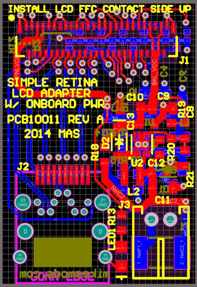
The most drastic change for this design is the integration of buck and boost power supplies to drive the panel and backlight respectively. I was not happy with telling people they’d need to provide their own regulated power – the panel isn’t THAT sensitive to voltage wobble, but it can be a problem with particularly long power leads, despite the large hold-up capacitor. Now the board should be able to take between 5 and 18 volts and spit out well-regulated rails.
Several other things have changed as well. I’ve changed the full-size DisplayPort connector to a miniDP connector, because for as small as the board is, the full-size connector was a waste of space. I’ve added a proper connector for power – while handing out boards with bare wires soldered on was functionally workable, it’s not exactly as clean a solution as I prefer. There is no longer a diode OR between external and DisplayPort power, because cables that carry DP_PWR are so uncommon that it is unnecessary. And there’s a fuse, to limit catastrophic failure in the event of a solder bridge or improper installation.
Now, the added components will increase BOM cost – I’m not sure by how much, but I know it will. However, I have designed in jumpers that will allow users who still want to feed in their own 3.3V and who don’t need a backlight supply to use this board in the same way as the old one. Hopefully this will make the design more accessible to people who want a more compact, all in one design without alienating those who like it how it was.
The design is a day or two from completion. As per typical, I’ll be building a board up and debugging it before I release the design documents, so that I don’t release something that won’t work. So keep an eye out in the coming weeks.
Ohhhh… would love to buy one of these if you’ve completed a couple – had been thinking (and wishing) that all of those making the retina pcbs should use minidp. Any plans on perhaps adding in the daisychain function?? (I know it would be a lot of work… and only helpful for those who have “Thunderbolt 2” ports…)
Scott
Daisy-chain (MultiStream Transport) is a major, major pain. There are not very many manufacturers who make MST splitters (I know of only ST), and they’re typically filed under ‘if you have to ask about this we’ll never sell it to you’… I asked my rep about a similar part once and got a 25,000 piece minimum order – I don’t think I want to be spending a couple hundred thousand dollars on parts for a hobby project!
For what it’s worth, though, you don’t need Thunderbolt2 to take advantage of MST; it’s a feature of DisplayPort 1.2 so any DP1.2 compliant source should support it (e.g. many modern GPUs). Assuming DP1.2’s maximum 4-lane bandwidth of ~17Gbps, you should be able to run three of these panels from a single port… if the controller supports MST, which this one does not.
I was reading the PCB10002_REVB project’s pages but now I think I will wait
for the completion of this.
Personally, I liked the idea to power the panel with the DP cable.
I read that there are non-compliant DP cables which connect pin 20 (DP_PWR)
but I do not know if such solution may have drawbacks (perhaps with
graphics cards).
I do not know if you will sell assembled boards. Please, let me know.
I am really interested to buy one.
Thank you for sharing your projects. I like the design of your website.
PS: electronics is not my field, do you think this device can be powered by lithium-ion battery.
My wish is to assemble a portable external display.
The problem with powering from DP_PWR is twofold. First, you need to locate a DP cable that connects DP_PWR, which is rare. Second, you can only get 500mA @ 3.3V from the DP_PWR pin even if it is routed, which limits you to powering the panel itself – the backlight draws an additional 4 watts which exceeds the port’s capacity by a lot. The only case in which using DP_PWR makes sense is if you can find a non-compliant DP cable that routes DP_PWR, AND you are not intending to use the backlight (such as in a DIY projector build). Granted, this was the initial target application for the little boards, but many people are using them as general-purpose interfaces, and that tends to get messy when you need to provide your own power rails.
What I can do, if you really, really still want this functionality, is try and squeeze in some 0-ohm resistor jumpers to connect DP_PWR to the 3.3V output. I’ll do that if I can route it to my satisfaction.
I will sell assembled boards if I can get ahold of stencils that I am happy with. The folks at OSH Stencils have challenged me to try them, and I plan to do so for this board. If I can’t get a stencil, I won’t sell assembled boards – the old, much simpler ones took way too much time, and these have many, many more parts. We’ll see.
As for powering from a battery, I think that’s a very reasonable request. Remember, the commercial use of this display (iPad) was powered from a lithium-ion battery. However, there are some limitations: it must be a two-cell series pack since the bottom end voltage I am expecting to support is 4.5 volts, and you will need to implement your own provisions for shutting the display off. The goal of this design is simplicity, and as such there are no controls and no power switch. Additionally the backlight current limiting is cheaply but wastefully accomplished through series resistors, not a proper PWM driver (there was not room for one on this board). So power consumption will be higher than it could be. You may be better off with a somewhat more complex board that implements both the controls and the backlight driver. But ultimately it depends on your design, and if compact size is important this is probably as good as it gets 🙂
Thank you for stopping by, and keep an eye out for the completed project (as soon as I have some time to complete it!)
Hi Mike, thanks for your detailed reply.
I do not really need DP_PWR. Now I understand,
the use of the DP_PWR made sense in the simpler version where the goal
was to interface with a DIY projector (eliminating the need of an
external supply).
Fantastic work Mike! I was wondering if you have looked at the IPad Air? It uses a new Sharp IGZO LCD with much lower power consumption and better light transmission. It has the same 2048 x 1536 resolution and 4 lane EDP connection as the Ipad 3/4 but appears to have a different connector that I have not identified. I am interested in a projector type application that would not require any backlight. I thought maybe I could use your board and make a cable adapter. Any thoughts on this?
I have not seen any information on this new panel. Do you have a part number for the panel and/or a link to a specification of any sort?
Presumably if the driving scheme is similar it shouldn’t be too problematic to adapt the board for the new panels… assuming we can buy the connector.
The most common screen part number is the LG screen: LP097QX2-SPAV
Unfortunately I have not been able to dig up a datasheet. Replacement screens are readily available via Ebay and other sources.
Here’s a test that provides some performance specs and discussion about IGZO technology:
http://www.displaymate.com/Tablet_ShootOut_3.htm
Here’s some basic specs:
http://www.panelook.cn/LP097QX2-SPAV_LG%20Display_9.7_LCM_overview_21631.html
Here’s a photo of the screen and 42 pin connector.
http://d3nevzfk7ii3be.cloudfront.net/igi/xTWKbhNULkRQZ3kY
Thanks for the information! I’ll look into it.
Good day and tell me whether your controller for Iphone LCD 5 ???
No, sorry. The iPhone LCDs have a different connector, and use MIPI DSI instead of DisplayPort for the data interface. This board is only intended for the iPad display.
When will you make the design files availible?
thanks
As soon as they’re done 🙂 I haven’t gotten around to finishing the design yet, unfortunately.
Hello Mike,
Great work, do you have an ETA when you will have these boards available?
Unfortunately no. I seem to have much less free time than I did when I started this website, it’s been hard to find the time to make any progress on it for several months!
Hey mike,
Do you have any of those boards available? either the old ones or the new ones?
I’d like to aqcuire one. Any word on price and availability for the new ones?
Nope, sorry, no boards available yet, and I’m not sure when it might happen 🙁
Hi Mike,
Any thoughts regarding adding a surface mount potentiometer for adjusting the backlight with a screw driver? Is it otherwise just a single brightness level based on the installed resistors? I’d be interested in buying two finished boards if you return to this project after your house move.
Thanks!
David,
The output voltage of the board (and thus backlight voltage) is indeed set by fixed resistors. I’m not sure a trimpot would fit on the board, it’s pretty densely packed… I’ll have to take a look and see how small of a pot I’d be able to get.
(This board wasn’t really meant as a “full-featured” solution, just something to power up the panel without forcing the use of bulky external supplies…)
Any news on when the board files will be avaible?
Is the board a two- or four-layer one?
-Jakob
Jakob,
All of my LCD-related boards tend to be four-layer, because it’s difficult to make a two-layer board with proper 100-ohm differential pair impedance as required for the high-speed DisplayPort traces. Now, truthfully, the one-inch of trace in the board probably doesn’t create enough of an impedance mismatch that the DP receiver in the panel won’t be able to figure things out, but the cost of the boards is pretty low even with four layers due to the tiny dimensions, so I consider it better safe than sorry.
I had actually forgotten that I hadn’t released the files already! Unfortunately since posting the article some of the parts have gone end of life so it will need some rework before I can push out the files. It shouldn’t take much, so I’ll try to get on it before too much longer.
Hi Mike,
Any news on when the board files will be avaible?
Sven
In the time since I started on this one, some of the parts have gotten difficult to source… I need to rework it, but I haven’t gotten around to it yet. Sorry 🙁
Is there any chance you’ll try to design a board for the touch screen, right now I’m using the Adafruit board but it would be great if we can also use the touchscreen to control the content instead of needing a mouse for that.
Strangely enough, I just yesterday started work on the touch panel again. Don’t get your hopes up for anything in the short term, but I am working on it 🙂
That’s great news, hope you have the time to do it.
Its very interesting not find any capacitive digitizer for that panel für windows. There are many Chinese tablets that runs dual os (x86/android) running lp097qx2. Example: TECLAST X98 9,7 or ONDA V919. Any news on your touch screen yet? whats your plans?