After screwing up and designing boards around an incorrect connector, and then when the corrected boards came in immediately leaving town for a week on business, I’ve at long last had some time to work on the Macbook panel. Spoiler alert: Some progress has been made.
If you don’t recall from previous posts, I threw together a quick board containing only DisplayPort and I-PEX connectors and a bunch of pin headers between them. The idea is that since we know where the DisplayPort connections are but not the order in which they are arranged, we can solder in jumper wires very easily to test the various lane orderings and polarities without having to otherwise modify the board. Here’s (the fixed Rev B version of) the board I used to figure out the pinout:
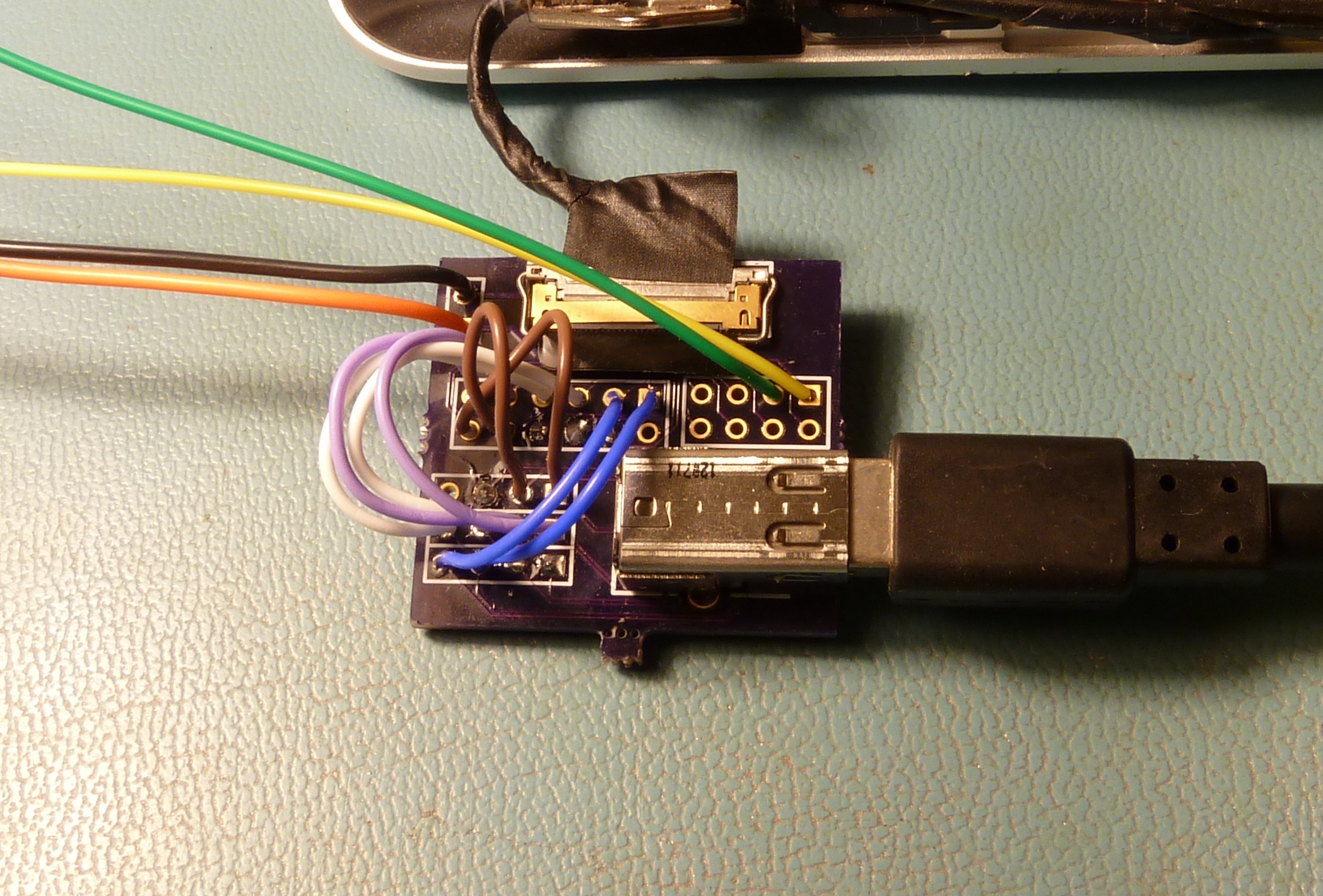
Assembled test board with all wires attached. I unfortunately don’t have a photo of the board prior to installing the wiring.
There’s nothing special going on here. At top, connected to the panel, is the I-PEX connector, with its known power and backlight pins hardwired in. At the bottom is a standard mDP, connected to the host PC. I connected all the wires I could – power and backlight of course, and AUX+ and AUX-. From there some engineering is required.
First, we look for Hotplug Detect. This pin should go logic high shortly after power is applied to the panel. There are only two pins left on the connector without a defined purpose, 9 and 10. In testing the panel, it is observed that pin 9 develops 2.8-3V, and pin 10 develops 1.4-1.7V. The latter is a bit low for HPD, so we will assume that pin 9 is HPD and pin 10 remains unknown for now.
With that pin now connected, we begin testing the DP lanes. Remember that logically, the lanes should be arranged in one of four orders: 0+/0-..3+/3-, 0-/0+..3-/3+, 3+/3-..0+/0-, or 3-/3+..0-/0+. I started with the first ordering listed. Interestingly, the display showed a half-inch of garbled blue blocks at the top and gray bands down the rest of the surface, but the display announced itself to the PC properly and I was able to set its properties. More boggling yet was that when I reversed the polarity of each of the four pairs, I got a different garbled top area (this time more like static) and the same gray bands, but equal operation with the PC. I had always assumed that the incorrect polarity would result in a completely inoperable display – interesting. But not yet correct. I tried the other two combinations, and neither of those would even bother to talk to the PC beyond sending EDID.
I panicked for a second here, thinking I’d have to try a lot more combinations of pinouts, taking a lot more work. I tried just connecting one, two or three lanes to see if that made any difference but the PC was unhappy with all of these tests. Finally I happened to glance at the analog ammeter dial on my bench supply and it was wiggling fairly wildly around the 300mA range. This didn’t seem right at all, and I immediately began to suspect the power I was applying to the panel (through about three feet of jumper wires to place it close enough to the DisplayPort source on the other side of the room). When I replaced the original pinout (with the blue blocks) and used about 8″ of hard-soldered wire and a local bench supply, and upped the current limit to about 1A, I was greeted with the following!
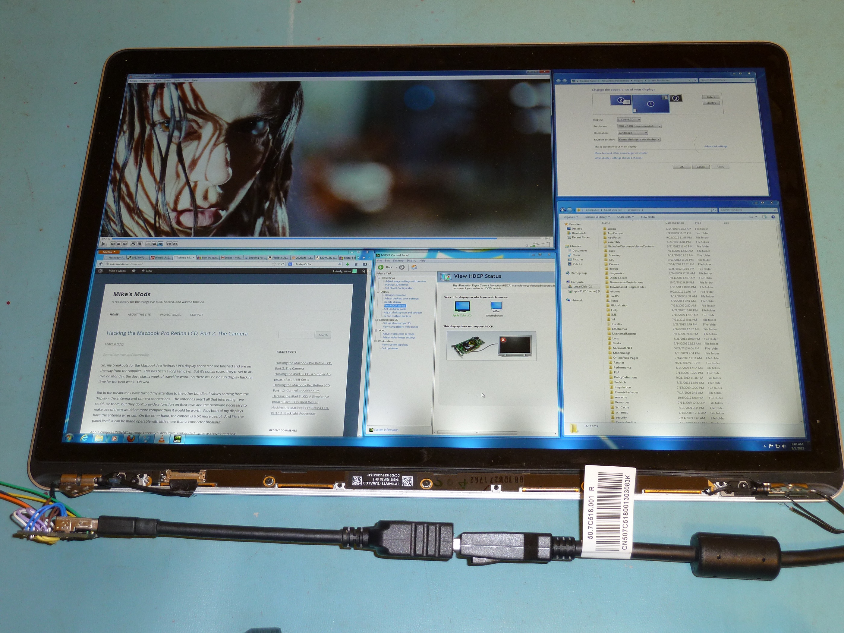
It works!
This just goes to show you how important it is to pay attention to the impedance and voltage drop of your wiring. Always use as short of wires as possible! Do note that I only connected one backlight string, which is why the banding is so bad; with the other five strings connected it probably wouldn’t be noticeable. It looks a little dark because I don’t have proper current limiting installed and I’m driving it cautiously.
So now we know the full pinout of the Macbook Pro 15.4″ panel (or, at least enough of it to get it running. Here it is, for your design and hacking purposes:
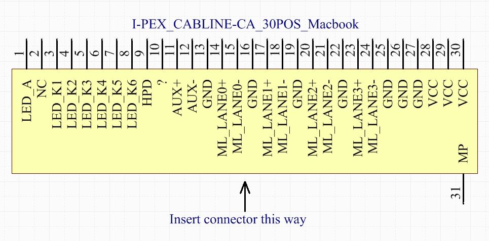
Not sure what Pin 10 is. Looks kind of like 0.5*HPD
Finally knowing the pinout, and running short on time before the next OSH Park 4-layer order, I quickly made up a proof-of-concept controller board for the panel. The board includes a Freescale MC34844A backlight driver, a Freescale Kinetis MKL25Z128 ARM Cortex-M0+ processor (again chosen for cost to performance ratio), independent switching supplies for the processor and for the panel (which requires a different voltage), mini-USB and mini-DisplayPort connections to the host PC, and a header to match the header on the camera board for the ambient light sensor. Special care was taken to cut costs on this board wherever possible without compromising functionality – the Linear Technology switcher from the iPad board was scrapped for parts a third of the cost, and some parts were increased in size to avoid paying the premium for the size decrease. With some difficulty the board was kept to the same compact 1.5×2.5 inch form factor as the full iPad board.

I don’t have many of the parts modeled yet. So sue me, I was in a hurry!
I will release the documents for this board as soon as I build one up and verify that it works – I don’t want anyone ordering a board which might not work. If you still really want them ahead of time to look at, send me an email.
<< Previous post in this series … Next post in this series >>
Very cool, really looking forward for new progress and
maybe I can order or build my own board 😉
grettings from Berlin
Feyco
I have the PCBs and components in house and am working on getting everything built and tested practically as we speak. Power supplies look good, next will be checking out the new backlight driver. If all goes well I hope to post my design documents next week sometime.
I wonder if it’s capable of running at greater than 60Hz. 🙂
Soon we shall see… boards are about 90% built up.
I’d like to buy one of these macbook lcd testers from you. If you’re interested, how much and how soon? Thank you.
To be quite honest, I haven’t yet considered what it would take to sell these boards. For one, they need a little bit of work before they can go out – the firmware on them is just complete enough to turn the thing on, but no more; also, some of the routing was not as ideal as it should have been. Then I’d need to draw up a BOM and calculate costs, bring in stencils, etc…
For a while I wasn’t planning on selling these boards, but an awful lot of people have been asking about them, so it may be getting to the point where it is worthwhile, but I haven’t started the process yet. All I can ask is for you to keep an eye out here for more information as it becomes available, or (if you need something a little sooner) all the documents are available here if you want to try your hand at building one yourself.
Hello,
I found the LP133WQ1-SJA1 panel datasheet at:
ftp://helpedia.com/pub/temp/datasheets/monitors/Panels/Panel_LG_Display_LP133WQ1-SJA1_0_%5BDS%5D.pdf
It is the LCD panel used in several models of MacBook Pro Retina 13″.
The pinout (page 22) seems identical to the one you discovered for LP154WT1-SJA1.
Perhaps it could help in understanding the function of pin 10 (Frame Sync mux).
This is the correct web link:
Although the link gives me trouble, I was able to navigate through the directory tree and grab the document. I’ll take a look tonight. Thanks!
HI Mike,
Where did you buy the ipex display port adapter?
Oh, I see.. you made it yourself.
Yep 🙂